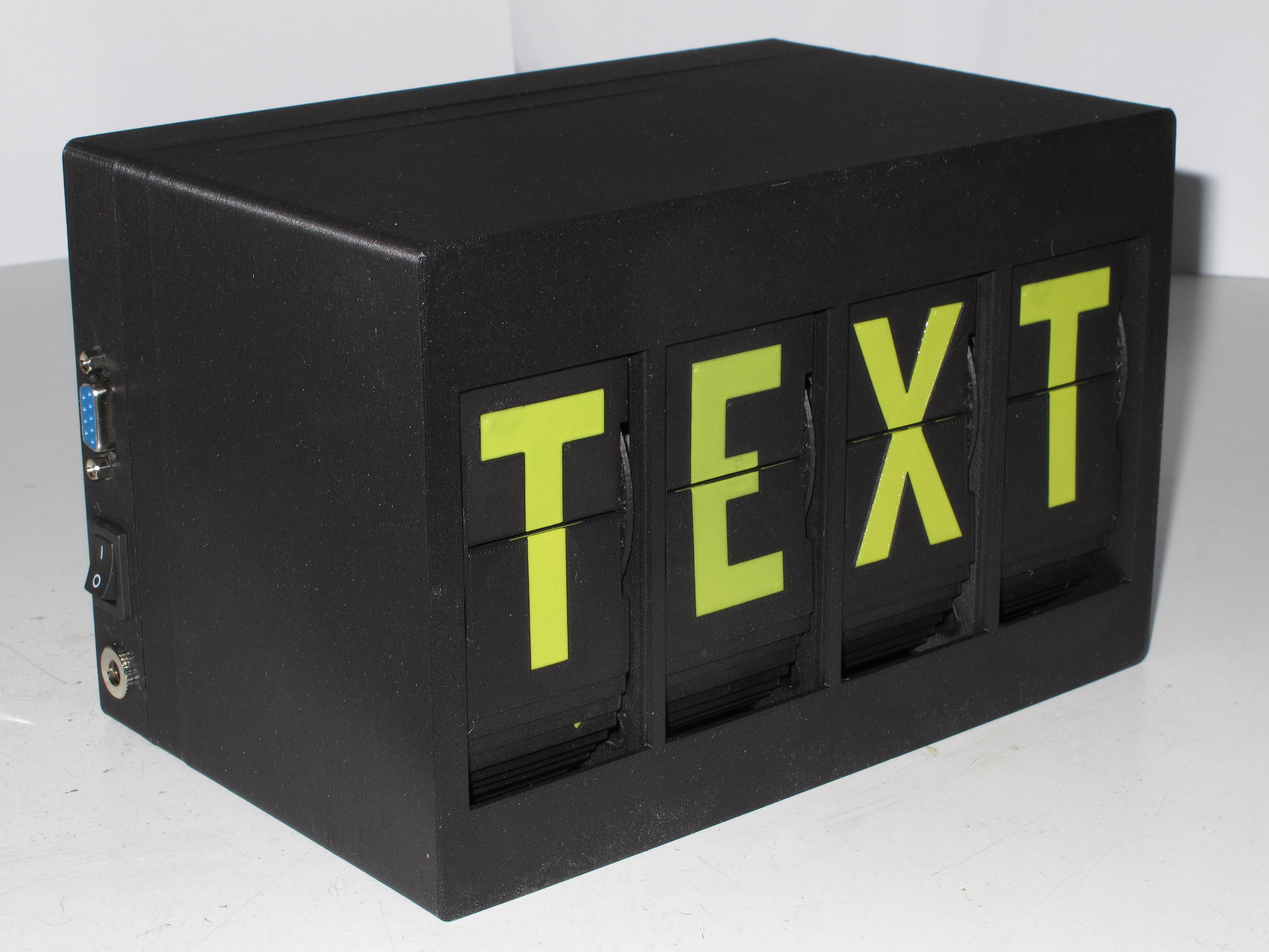
4 Letter Split-Flap Display with RS232 UART & Daisy-Chaining
by Arne · via Printables
| Format | STL |
| Category | Electronics |
| License | CC BY-SA |
| Triangles | 8.4k |
| Uploaded | Jul 26, 2025 |
⬇ 10 downloads
❤ 4 likes
👁 162 views
Description
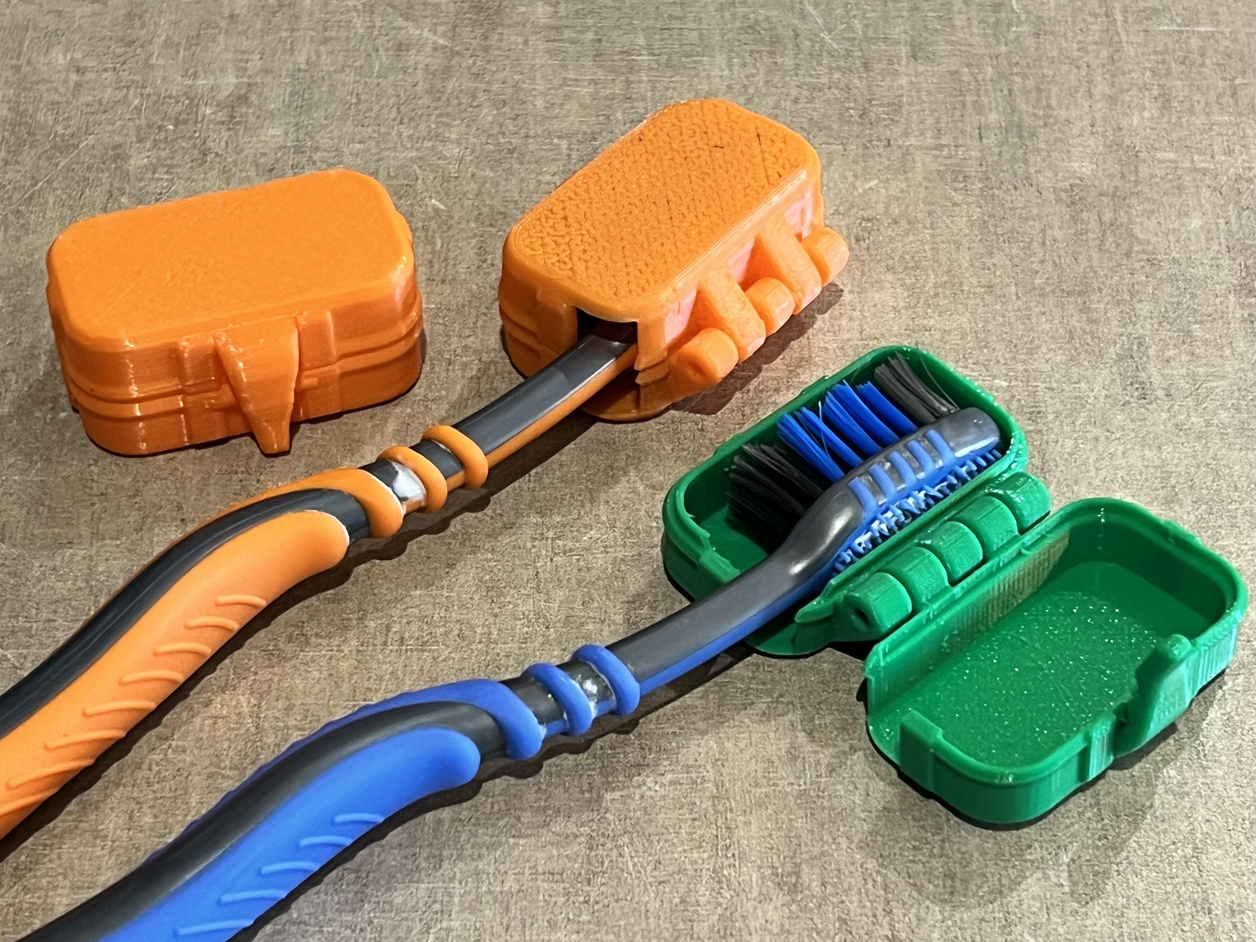
Overview This is a modified version of David Kingsman's split-flap display. I made these changes: Unit: Changed the parts to accept 3mm self-tapping flat-head screws (no threaded inserts needed). Removed the small protrusions at the bottom of the motor mount as they interfered with my motors. Case: Modified the case for 4 letters, and made the right outside wall the same thickness as the left (this uses a bit more material but looks nicer). Changed the hole sizes for the DC connector and switch to fit the components I had in stock, and added a hole for an RS232 DE-9 connector. Electronics (optional): A simple controller PCB that can handle (up to) 4 letters and can be daisy-chained for arbitrarily large displays. Changed the control port from I²C to RS232, removing the need for setting an address on each PCB. It's also possible to use the modified 3D models with the original controller PCBs. Printed Parts for a 4-Letter Display 1x MiddleFrame_4 1x FrontCover_4 1x BackCover_4 4x UnitFrame 4x FlapDrumInner 4x FlapDrumOuter 4x Set of flaps (I used https://www.printables.com/model/518892-more-split-flap-flaps-on-build-plate ) Required Hardware Try to find screws with a flat end. Example source: https://www.aliexpress.com/store/1103417133/pages/all-items.html?productGroupId=40000006441517 . Magnets: https://www.ebay.co.uk/itm/204451375924?var=505035714721 . For each unit (letter): 2 screws, self-tapping, pan head, 2.2 x 5 mm (sensor) 4 screws, self-tapping, flat head, 3 x 10 mm (motor, drum) 4 screws, M3 x 16 (mount unit to frame) 4 nuts, M3, hexagonal (mount unit to frame) 1 magnet, 2 x 1 mm For each four letter group: 4 screws, self-tapping, pan head, 3 x 8 mm (mount PCB to one of the units) For the 4-unit case: 8 screws, self-tapping, pan head, 3 x 16 mm (frame to case front, case rear to front). Required Electronics Bill of materials for one 4-letter controller board: Qty Part LCSC # 1PCB (or piece of perfboard) 1ATmega8 or ATmega8A (DIP-28)C34931128-pin narrow IC socketC721252ULN2803 (DIP-20)C75528178L05 (TO-92)C579002Transistor BC547C (or BC548C, BC549C, BC550C) or similarC32015501Quartz Crystal, 14.7456 MHz (HC-49U or HC-49US)C112332Capacitor 22 pF (2.5 mm pin pitch)C28325104Capacitor 100 nF (2.5 mm pin pitch)C28325061Capacitor 470 nF (2.5 or 5 mm pin pitch)C56324331Capacitor 470 µF, ≥16V (10 mm diameter, 5 mm pin pitch)C3381889Resistor 4.7 kΩC572042Resistor 100 kΩC585972Resistor 220 kΩC586621JST XH header, 4-pin (or compatible “XH-4A”)C378155JST XH header, 5-pin (or compatible “XH-5A”)C23184Pin header, 2.54 mm pitch, 4 pinsC2691448 Other parts: Qty Part Source (Example) 4Stepper Motor, 28BYJ-48 12V, exactly 1:64 gear reduction, with XH 5-pin plug https://www.ebay.co.uk/itm/191877872357 4Hall sensor modules, KY-003 https://www.aliexpress.com/item/1005006396288261.html (Note: I received latching sensors from this seller)4Harness, “Dupont” 2.54mm 3-pin female on both ends, 30 cm (for hall sensor connection) https://www.aliexpress.com/item/1005008319756738.html 1Harness, JST XH 4-pin plug to open ends, 30 cm long, 22AWG ("XH balancer cable") (for power & RS232 connections) https://www.aliexpress.com/item/1005006095397387.html (select variant “3S”)1Power connector (for 11 mm diameter hole) https://www.aliexpress.com/item/4000559875991.html 1Power switch (for 19.2 x 13 mm hole) https://www.aliexpress.com/item/32873386670.html 1Connector, DE-9 female, solder cupLCSC C4968991D-Sub mounting kit (2x standoff, 2x nut) https://www.aliexpress.com/item/1005006341987402.html 4-Letter Controller Board My 4-letter controller uses a simple circuit based on an ATmega8. You can build it on perfboard like I did, or send the Gerber pack to your favourite PCB manufacturer. I ran out of I/O ports on the microcontroller, so two hall sensors share a single port (using two series resistors and the internal ADC). I was too lazy to implement a homing sensor calibration value in the software, so instead I moved the hall sensors until the position was correct. Have a look at the photos to get a rough idea where the sensor needs to be located. The sensors I received appear to be the latching type, so I oriented the sensor vertically. This way, the magnet sets the latch when approaching from one side, and resets it once it has moved to the other side of the sensor (try this before gluing the magnet, as it only works when the correct side of the magnet is facing the sensor). When connecting the hall sensor modules, make sure the pinout is correct. If you keep the Dupont connectors on both ends of the cable, you might have to remove and re-shuffle the pins on one side to get the correct connections. The pinout of the headers on the controller board is 1=+5V (closest to board edge), 2=GND, 3=Signal. The sensor modules usually have the pinout printed on the PCB. If you want to use it for a display with more than 4 letters, simply daisy-chain the UARTs of the controllers: TxD from the D-Sub connector (pin 3) is wired to RxD of the first (leftmost) controller, TxD from this controller connects to RxD of the next controller and so on, and TxD from the last (rightmost) controller is wired back to RxD on the D-Sub connector (pin 2). To display text, simply send it to the RS232 port, followed by a line break (CR or LF). The default baud rate is 9600, but this can be changed in the source code (but don't set it too high, the simple transistor circuit isn't very fast). The daisy-chaining works by each controller keeping the first 4 characters after a line break to itself and forwarding on any further characters it receives. Control characters (ASCII 0x00~0x1F) and escape sequences are always forwarded. The following additional ASCII control characters are supported: CR, LFClears the remainder of the display (if the message is shorter than the display) and will accept a new message. Sending more than one line break (e.g. CR followed by LF) will clear the entire display.NULLike above, but ignores any more text being received until a <CR>, <LF> or <FF> is received.FFClear entire display. For more advanced functions, these escape sequences can be sent: <ESC> 4 1 Turn Four Letter Word (FLW) mode on (display a random four letter word from a dictionary in an adjustable interval). <ESC> 4 0 Turn FLW mode off (default). <ESC> 4 . Display a random FLW right now. <ESC> D xxxx FLW mode interval in 1/10s, xxxx = 0001~FFFE (hexadecimal, converts to 0.1s~6553.4s). Default is 30s. <ESC> S xx Motor speed in F_CPU/128 ticks, xx = 01~FE (hexadecimal, converts to 115200~453 half-steps per second at 14.7456MHz CPU clock). Default: 1200 half-steps per second ( xx = 96). Reduce the speed (increase xx ) if the drums get stuck too easily. The escape sequences are sent through the entire daisy chain (and back to the host), so the entire display is using the same settings. Each controller saves its settings in EEPROM, so you only have to set them once.
Originally published on Printables