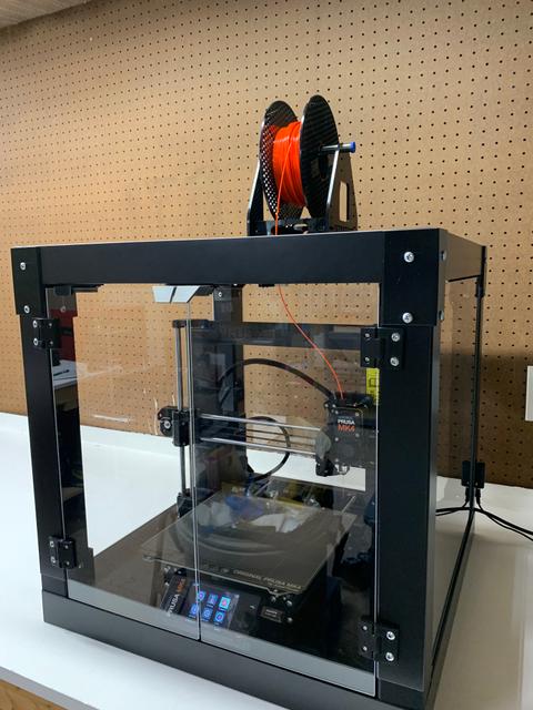
A structurally sound yet elegant lack enclosure
by Alec Warner · via Printables
| Format | STL |
| Category | Art |
| License | CC BY-SA |
| Uploaded | Jul 28, 2023 |
⬇ 89 downloads
❤ 33 likes
👁 1.5k views
Description
A quick background: After doing a build of the Prusa v1 lack enclosure, I was disappointed by how loose and fragile the whole thing felt. It almost seemed that if I were to try and move it, the legs would snap right off. The acrylic panels were at spots so loose that the doors all too often would fall out of their hinges when opened. Long story short, this enclosure assembly guide aims to improve upon the lack tables benefits while overhauling the structure to make it feel like less of a project and more of a cost effective alternative to premade enclosures. Prints: Hinge options https://www.thingiverse.com/thing:2458221 Door handles https://www.printables.com/model/269670-ikea-lack-door-knob-and-handles-magnet-inserts All prints are able to be done without support but build plate support might be helpful when doing the bottom enclosure corners. Enclosure assembly: After printing out the main pieces (top+bottom corners, top reinforcements, bottom plates) the legs need to be partially assembled before screwing them into the main part of the lack table. For each leg place one of the top corner pieces on the end which came pre drilled and begin threading one of the included double sided lag bolts through the printed part and into the leg. This will most likely require a large pair of pliers and or a wrench of some sort. It is important to make sure that a gap doesn't begin to form between the printed part and the leg as the lag bolt threads in (I used long clamps to hold them together during this threading process). Once the midpoint ridge on the double sided lag bolt reaches the printed part and is snug you should stop screwing (the other half of the bolt should be sticking out). This whole process may take a bit but is what will make the enclosure strong. To finish prepping the legs, screw two of the #10 screws into each just as you would with the original lack build. If running wires through one of the legs it is easiest to to fish it through before mounting the legs to the top of the lack table. With all four legs ready they can be screwed into the base just like a normal lack table would be assembled. If the legs are fully screwed in and not in the right position for the acrylic panels you may have to apply extra force and continue tightening until they're at the necessary angle. Installing the top corner reinforcement pieces can be done at pretty much any point moving forward but doing it now might prevent the acrylic panels from getting more scratched. The only thing to note about these is that the side with mounting hole close to the edge goes into the leg while the other into the main part of the lack table. (predrilling may help these to sit a bit more flush with the corners of the lack table) At this point with the enclosure upside down the acrylic panels should be placed into their slots, allowing the top (actually bottom) corners to be mounted onto the legs using three of the #10 screws for each. Screwing into the bottom side of the legs shouldn't require a pilot hole, just be careful not to overtighten these as there is less than an inch of mdf in the base of these legs. The corner plates should now be added to the top of the second lack table (enclosure base) using the same #10 screws (I drilled out the center layer on the bottom plates beforehand to make mounting and adjusting easier). These holes do not need to be pre drilled into the base but it may help them to sit more flush than self tapping. (Note the orientation of the power pass through plate in the back right) Placing the top body of the enclosure onto the base, ensure that everything is for the most part aligned. Assuming everything looks good, do a dry fit of the doors to determine mounting locations for the hinges as well as the magnet mount. (I opted to locate the door handle pieces on the tops of the doors as to not block the display/lights. Doing this also allowed the printer to move forward just over 1cm, alleviating some of the strain on the heatbed connector in the back.) Having figured out where the hinges should go, they can be attached to the acrylic door panels using a drill bit just larger in diameter than the M3 screws. It pays to take extra time getting the hinges perfectly lined up and symmetrical on the door panels. With the holes drilled each backing plate can be placed and the 10mm M3 screws should be carefully tightened, sandwiching the hinge, acrylic, and back plate between the head of the screw and the square nut in the back. These should be snug but not so tight that the prints or acrylic start to break. To mount the doors to the enclosure, use a wide spacer of some sort to ensure that the door is parallel to both the top and bottom lack tables. Once everything looks good placement wise, slightly predrill the holes into the lack legs and use the same #10 screws. Wait to fully tighten these until all four on that side have been put in and the door is adjusted to your liking. As you fully tighten these four screws be careful not to strip out the thin walls of the lack legs. At this point, finishing touches such as the door holding magnet mount can be installed along with any sensors, wiring, filament pass through, or vents. Required materials: 2x Ikea lack table (comes with the double sided lag screws) Filament I used Prusament jet black PLA at 20% cubic infill for everything except the hinge and door handle parts. For these I used a combination of gray and black PETG as they will get more wear over time. Acrylic panels https://www.printedsolid.com/products/acrylic-sheets-for-prusa-lack-enclosure Wood screws #10 x ¾ in (you need lots of these, I just picked up a 100 pack) Door screws 8x M3 10mm screws Door nuts https://a.co/d/d4UTvsu Magnets https://a.co/d/1OEGyRv Super glue and hot glue Optional basic ventilation: This design is very simple and intended to be glued into place with the exception of the top filter cover which attaches with 4x M3 4mm screws. If you are looking for serious filtering of the air I would find a larger hepa filter design elsewhere. The idea of this design is to be mostly hidden into the lack table itself in an effort to maintain the clean aesthetic. In my case a multitool worked well to cut a clean square hole through the lack table. If your hole on the underside of the lack table isn't the exact size of the main insert, the sealing ring can be glued around the inside to cover the gaps. I cut some spare 1cm thick carbon filter into a square slightly larger than the inside of the vent housing. The fan and filter can be added into the vent stack along with the 60mm printed spacer to keep things from moving around too much. Sensors and such (the fun stuff): These parts are by no means required for this build but can be copied or used as inspiration for whatever components you choose to put inside. For my setup, I used a 5V 3a basic dc power supply to drive all of my accessories. Since I am running a home assistant instance on my network, I chose to use that as the management system for the all of the devices via ESPHome running on a d1 mini (esp8266). Wired into the d1 mini is the magnetic door sensor, DHT22 temp+humidity sensor, 1m (60 pixels) of addressable led strip, and a Noctua 5v 4-pin pwm 60mm pc fan. Using home assistant allows me to monitor the enclosure temps remotely and if desired send notifications based on different enclosure temperatures. The enclosure fan turns on once the enclosure begins to heat up, helping to regulate the internal temp and filter the warm air as it's exhausted out of the top. To keep the look of my enclosure clean and without wires, I ran the low voltage cable through the back right leg, mounting the dc power jack towards the bottom of the leg. Because I ran this cable through the leg before attaching it to the rest of the enclosure I used a small terminal strip to make the low voltage connection after assembly. Components: Use any decent d1 mini (or other microcontroller) 5V power supply https://a.co/d/7LPmPGI Addressable led strip https://a.co/d/iMg072r Temp and humidity sensor https://a.co/d/7mXEkBS Door magnet sensor https://a.co/d/dt3cUzb Fan https://a.co/d/hzpmVMT (if fan doesn't have built in pwm support, an additional relay or transistor driver is required) Super in depth tech note about this microcontroller use case: Since I am using a d1 mini which runs an 8266 microcontroller, it doesn't have a built in pwm timer chip and as such if you want or need speed control of the fan you will have to run software based pwm. Normally this wouldn't be an issue with things such as leds but with the 25kHz pwm frequency required by 4 pin pc fans, it causes a bit of lag when the d1 mini is controlling multiple outputs at once (ie. led strips are on and fan is running at a value other than 0% or 100%). If running the fan at 100% is an issue for your setup the esp32 includes hardware pwm timers capable of 25kHz and would be a better option. Cool printable add-ons: X axis motor strain relief for MK4 (m3 screw) https://www.printables.com/model/502616-prusa-mk4-cable-support-x-axis Simple filament guide/pass through (glue in place) https://www.thingiverse.com/thing:1895060/files Lack leg support (good for lack stacking, wood screws) https://www.printables.com/model/23385-ikea-lack-enclosure-reinforcement-supports DHT22 sensor case https://www.thingiverse.com/thing:4521313
Originally published on Printables