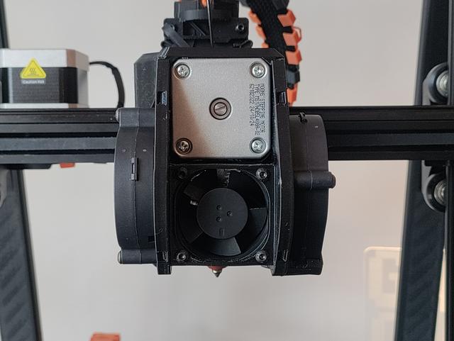
Combined FatBurner with 40mm fan mount and duct
by Entharion · via Printables
| Format | STL |
| Category | Art |
| License | CC BY-SA |
| Triangles | 12.8k |
| Uploaded | Jan 27, 2026 |
⬇ 71 downloads
❤ 13 likes
👁 389 views
Description
Background I bought the Ender3 V3 KE this year (2025) and it seems the original FatBurner toolhead cover is not fully compatible with my revision of this printer, so I ended up printing Ronald Rademaker's combined version. It fit and allowed me to upgrade my fans to 2x5015 partcooling and 1x4020 hotend fans, but I saw room for improvements. Why it was remixed I wanted to make some modifications to his model because it had some clearance issues on my printer. Mainly I fixed the x-axis endstop clearance and the fitment around the extruder motor. I also found that the fan I chose (Sunon maglev 24v 1.2w) was a bit loud because the airflow was obstructed by the screws to mount it to the heat break from the shroud that Fatmax suggested on the original FatBurner model. So I made additional modifications so the fan sandwiches between the bracket and the shroud, making the fan attach to the toolhead cover instead of the heat break, it places the fan slightly further forward as well so the new shroud should offer more volume and less obstruction of airflow, reducing noise. Print instructions Preferably, print the fan shrouds in PETG or higher temperature filament since they're closest to the heater, PLA should do fine for the toolhead cover, but no guarantees. Print the toolhead cover oriented as provided (upside-down) with supports enabled for most reliable results. I used 4 walls with 30% 3D honeycomb infill, but you could sacrifice weight for the sake of rigidity and increase it. Required materials 1 x 4020 fan (4010 fan theoretically works, but sub-optimal) 2 x 5015 fans 4 x m3x25mm screws for mounting the 5015 fans 4 x m3x20mm screws for mounting the 4020 fan Installation instructions Install the ducts and the fans to the toolhead cover beforehand, making sure the wires are long enough to reach the board on the left-hand side of the heatbreak and the connnectors are of the correct type (JST 1.25). While mounting the heatbreak fan, make sure the outlet of the shroud is aligned to the top-left corner. There's little channels in the cover that can help you guide the fan cables to the rear of the toolhead. After you've installed the fans and everything is assembled you can simply slide the cover over from the front, be careful not to pinch or damage any cables during this process. At some point you'll want to plug in the cables before completely covering up the board, I've personally routed the cable for the right-hand fan around the back of the heatbreak, it's a bit fiddly during installation but I've now done it multiple times without issues. After the cables are installed you might want to do a little start-up test to make sure the fans turn on, if everything works slide the cover all the way back until you can fasten the cover with the original toolhead cover screws. Additional notes For anyone wondering, the fan connectors you need for the Ender3 v3 KE are JST 1.25. Special thanks to Fatmax, powARman and Ronald Rademaker for sharing their work.
Originally published on Printables