Drill Guide
by Hank · via Printables
| Format | STL |
| Category | Tools |
| License | CC BY |
| Triangles | 25.9k |
| Uploaded | Dec 12, 2024 |
⬇ 157 downloads
❤ 178 likes
👁 3.6k views
Description
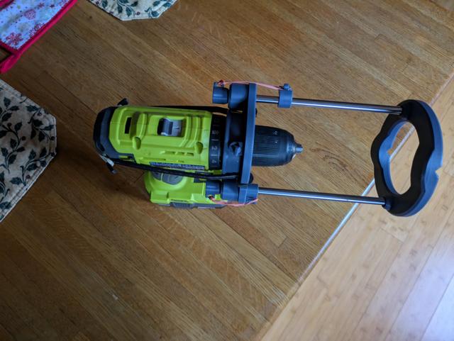
I liked “Teaching Techs” concept but thought it could be significantly simplified. I initially evaluated just reducing the Guide Rails to 2 but then decided also to eliminate the joints in the model. The Adapter aligns to the front of the bezel used to set the torque value for the drill. This ensures the guide is perpendicular to the drill. Retaining Straps are used to secure the Adapter to the drill. The straps run along the relatively flat sides of the drill held in place with elastic bands. The printed Thumb Screws are then installed to lightly contact the bezel (these replace the jaws used in the original model) and act to prevent the Adapter from moving. Hardware Required: (2) 8MM x 200mm Guide Rods - uxcell 2 Pcs Linear Motion Rod Shaft Guide 8mm x 200mm (0.315" x 7.87") Case Hardened Steel Chrome Plated, Metric Linear Rail Rod for 3D Printer, CNC Machine: Amazon.com: Industrial & Scientific (2) 8MM ID Linear Bearing - I recycled a couple of bearings I had replaced on my Prusa MK3S+ printer. Printing Printed in PLA using .3 or .4 mm layers with 2 perimeters and 15% infill. Recommend using supports and a brim for the Retaining Straps . Assembly Print parts and remove supports Install bearings in Adapter and make sure they are seated to the bottom of the Adapter . Install the Guide Rods into the Base . Add Depth Stop guide to rail (optional) Install Adapter on Drill and secure using Retaining Straps and elastic bands. Install & adjust printed Thumb Screws to stabilize the Adapter . Mount Adapter on Guide Rails . Mount Rod End Caps on Guide Rails and install elastic bands between End Caps and Adapter .
Originally published on Printables