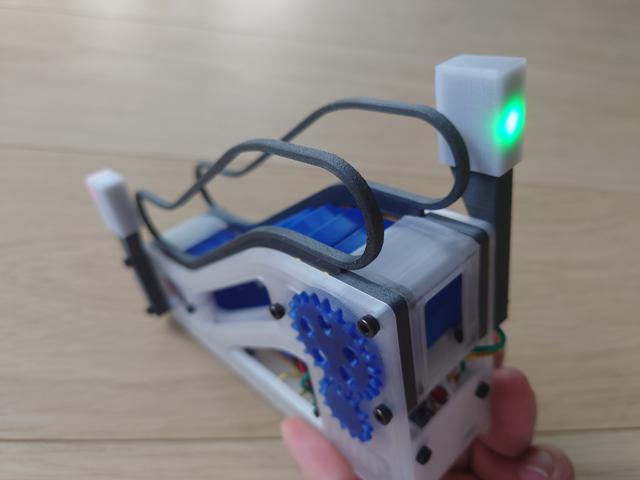
Escalightor: signal lights for motorised desktop escalator
by matemaciek · via Printables
| Format | STL |
| Category | Electronics |
| License | CC BY |
| Triangles | 1.8k |
| Uploaded | Aug 24, 2022 |
⬇ 42 downloads
❤ 16 likes
👁 845 views
Description
Project info Motor in original model is connected in a way that allows it to spin in both directions. We can use that to connect LEDs parallel to it, and thanks to their property of passing current in only one direction we can connect two colours in oposit directions to indicate motor direction. Design is not limited to escalator model, this can be used as a generic direction sign. (Let me know if you need part without bolt holes or OpenSCAD source file.) Assembly instruction Below are instructions for making one light, but for this model it makes sense to make two, one for each end. 0. Gather materials: 1x each of four printed parts. I used PETG, but PLA should also be ok. Black parts should block the light, white part (named Box ) should slightly diffuse it. Experiment with different filaments for best effect. 2x M3x20 bolts. 1x 5mm red LED. 1x 5mm green LED. 1x resistor suitable for your LEDs. Usually any value between roughly 20 and 500 Ohm should be ok, experiment with different values to achieve best result. I used 24 Ohm and it's almost to bright. 2x wires. I used 22AWG size. 📷 Image redacted — claim this model to add your own media 1. Push LEDs into Insert part Green behind the arrow, red behind the octagon. Or go wild and mix them. Observe polarity - one should be placed reversed w.r.t. the other. 📷 Image redacted — claim this model to add your own media 2. Solder components Bend LED legs as on picture below. Solder each pair of LED legs together (green cathode to red anode, red cathode to green anode). Add resistor in series, doesn't matter on which leg. Solder wires. If your connections turned out bulky, you may want to put shrink tubes on them. 📷 Image redacted — claim this model to add your own media 3. Test it Connect it to some 5V source, confirming that both directions turn respective LED on. Put the Cap part on the back of Insert part. You don't need to glue them. Slide both parts into Box , the fit should be satisfyingly tight. You can now test wether you're satisfied with light diffusion - just don't push parts all the way until you're sure, they may be hard to remove later. 4. Assemble it Bend legs slightly, as on picture below. Push Insert and Cap into Box , all the way. Thread cables through Leg and push it into Box . 📷 Image redacted — claim this model to add your own media 5. Mount it Lay the escalator model on the side. Unscrew two bolts on the end. Put assembled light on top, screw using M3x20 bolts. Solder parallel to motor, observing polarity. 📷 Image redacted — claim this model to add your own media 📷 Image redacted — claim this model to add your own media
Originally published on Printables