LiIon 18650 Filament Feeder for Bowden Loading (Extruder or MMU etc.)
by Tritschi · via Printables
| Format | STL |
| Category | Art |
| License | CC BY-NC-SA |
| Triangles | 7.1k |
| Uploaded | Jul 28, 2025 |
⬇ 181 downloads
❤ 80 likes
👁 2.0k views
Description
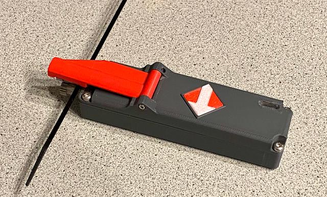
After 1 ½ years of posting my Motorized Filament Feeder, a new machine was posted in Printables. The “Bowden Speed Loader for Prusa XL and CORE One and similar for loading filament” designed by @MrFlippant inspired me to do a Printables Make. After I printed this, the 9V battery seemed a bit lousy as power supply. After chatting with @MrFlippant we agreed upon a remodel in LiIon battery direction. I want to give big credit to the creator of the original, whitout him I could not make this happen. Feeder consists of following components: 3D-print part “Base” - contains all purchased parts 3D-Print part "Top" - contains the operating arm 3D-Print part “Arm” - contains the bondtech gear with needle bearing and axle ø3x20 3D-Print part “Light” - shall be printed in Transparent PLA/PETG and is glued into the small square hole of the “Top” 3D-Print Arrow_Arrow and Arrow_Base - Print this separately and glue into place of “Top” when you are done with feeding direction. 3D-Print part “Base(Old)” was forseen for LiIon cells without remarkable tip at Plus. You should not need this. 3D-Print part " Purchased parts, I add a copy of MrFlippant's post: NON-affiliate Amazon links: GA12-N20 500rpm @12v gearmotor (check the speed and voltage before buying!) MK3s+ style Dual Drive Gear Hinge Lever Momentary Push Button Micro Limit Switch AliExpress links GA12-N20 500rpm @12v gearmotor (check the speed and voltage before buying!) MK3s+ style Dual Drive Gear Hinge Lever Momentary Push Button Micro Limit Switch You also need four (4) self tapping screws or adequate. I used self-tapping screws of @2.8x7mm, Torx 10. Then two (2) small self tapping screws for the hinge of the arm. Cable wires and solder. And some standard tools. NOTE: This is a description how I did the build, is not neccessarily a procedure which is technically correct or proven. If you are not familiar with electronics you should have this done by an competent person. I do expclicitly not take any responsibility on function and malfunctions and jeopardy you might run into, by either a bad description from myself or a mistake by you! Bear this in mind!! Prepare the threads for 4 screws by heating up the screws and carefully make the threads. This prevents you a later break of the part! The “Top” part has a square cut-out for having the part “Light”. "Light" is a little cube that should fit into the sqare hole, printed in transparent PETG / PLA. Then during charging of th ebattery you can see the indictor lights RED for charging and BLUE for ready. I have a clear UV-hardening superglue, not too liquid (high viscosity). I securely sealed the square hole with some Scotch tape and poured some superglue, hardened it with a UV-light. This is a quicker and better method in my opinion. Light shines through much better than PETG or PLA. “When gears are left, the minus (spring-part) is oriented on the right side”. After printing the parts start soldering the setup. Bear in mind, that you do not have much space left for stuffing the cables! I would recommend to connect a 4VDC power (LiIOn or external PowerSupply (PS)) so you can already test the motor and its speed. I use a 6VDC motor and power it by the step up module to 9VDC. You can check with a voltmeter what voltage comes out of the step up module. A small screwdriver will be used to adapt the voltage to your desire. Use the screwdriver on the blue potentiometer. I started inserting the pole (+ / -) taps into the slot. Needs a bit care to do. Hope your printer is very accurate. When gears are left, the minus (spring-part) is right. 📷 Image redacted — claim this model to add your own media Solder on TP 4065 wired that are soldered to the tabs plus / minus: B+ and B-, “b” like in Battery. Omit the left parts of "5V 1A DC", that is for external power supply other than USB C. Prepare also OUT+ and OUT- wires for the connection to the step-up module MT3608. Keep wires short as possible. Connect B+ to VIN+. and B- to VIN- 📷 Image redacted — claim this model to add your own media This is how awful my setup looked like. 📷 Image redacted — claim this model to add your own media Now you're set to connect V OUT + and V OUT - through the bottom part, called “Base”. Plus wire (e.g. red) goes to LimitSwitch "C tab. A second wire (e.g. red) goes to the motor tab, either minus or plus, depending on your desired feed direction (to left or right). This can be changed after the test is positively done. A (black) wire goes from VOUT- (minus) to the second motor tab. That is it. The limit switch needs to be in its position, free flag showing towards gears direction. Insert the LiIon battery 18650, check for short cuts and funtion. Operating the limit switch should turn the motor. This is a good moment to decide the direction of the motor. If you are satified with your setup, direction of motor revolution - then bend the tabs of “Plus and Minus poles” of the battery so they lie on the battery and are stuffed under the coming “Top” part. Now you need to put all the wires in a good order so that no insulation accident can happen and the the “Top” part can be set on the “Base”. Pay attention that the step up module is in its utmost left position and “stays there”, otherwise the possibility of regulating the rpm through the small hole in the right hinge is gone and you need to open it, which can be a PITA. The TP module shall be utmost right, the left small nose shall be in the groove, completely down, I always heard a little click. Now screw in the self tapping screws (4x), make sure no gaps are left. The bondtech gear with needle bearing and @3x20 dowel pin is clicked into the “Arm”. Note the direction. I did it gear showing towards battery, and not outwards, maybe both will work. Next install the "Arm" to the hinge and fasten it with some small self tapping screws. Make sure the hinge works quite friction less. I did not really achieve this, my “Arm” was always slightly jamming somewhere. Add the bondtech gear with the 3D-printed “Drive Shaft Adapter” on the axle of the motor, such that the grub screw contacts the flat part of the axle for torque. After you bring the “Arm” to operating position, the limit switch should work and start the motor. Often the “Arm” does not go back because of the low spring force of the limit switch. I added little foam pieces (black" before the hinge, so a little force is to be overridden. Look at the photographs provided. NOTE : Pay attention, the motor is quite strong, you may get hurt if you are not careful! Per smal screwdriver you should be able to vary the rpm of the motor, such as feeding speed. Once you are happy with everything, also direction, glue the arrow plate with arrow (bi-color) on the “Top”-part. If you want to change direction, just turn the machine 180° in along the long axis! In case you need more info, I refer to the original creator: https://www.printables.com/model/1219294-bowden-speed-loader-for-prusa-xl-and-core-one-and Good luck with the build and happy printing! Explore my other Printables: https://www.printables.com/de/@Tritschi Technical Data original compared to my remake: 28mm vs. 30mm width 26mm vs. 28mm height 115mm vs. 132mm length
Originally published on Printables