Little Boy S ATX PSU Single Full PCIe 220x220mm Bed Optimized
by beckhdtm · via Printables
| Format | STL |
| Category | Other |
| License | CC BY-NC |
| Triangles | 59.9k |
| Uploaded | Oct 24, 2025 |
⬇ 36 downloads
❤ 7 likes
👁 360 views
Description
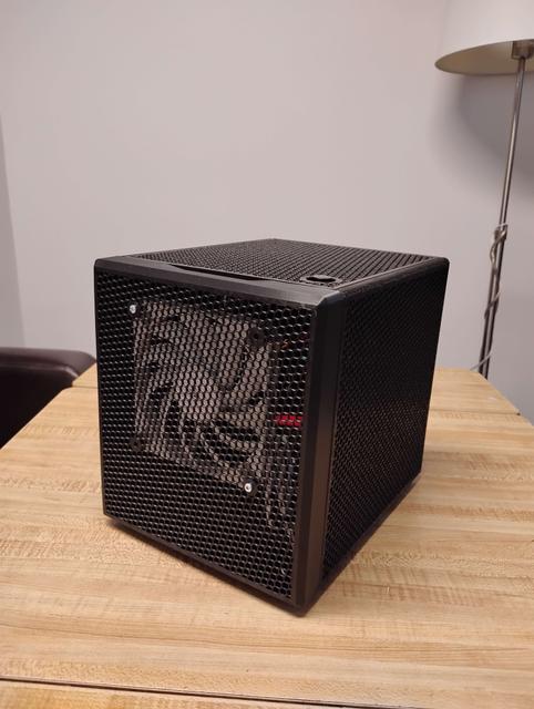
LIGHT BOY S FULL ATX PSU SINGLE FULL PCIE Every piece as been remodeled from scratch for a 220mm x 220mm bed size. 0.3mm tolerances. (loosy goosy for the lazy people, like me :) ) Accommodates 2x 120mm slim 15mm height fans located on front and bottom. One full-height single slot PCIe. Assembled dimensions are 244mm deep (front panel to back panel), 195mm wide (side panels), 224mm height (including feet). This is printed on a Sovol SV06. PLA+ is fine for this although depending on the motherboard VRM placements, PETG may be required for the motherboard side panel. Printed with 0.6mm nozzle, 6 walls, 20% honeycomb infill, 0.2 Layers. Component Dimensions and Notes Full size ATX PSU max depth of about 160mm. Cable management would be areas around the front panel fan and underneath the PSU CPU Fan max height is about 85mm (this is touching the PSU) Realistically for air flow about 65mm Single full size PCIe slot max dimensions Length of about 225mm Thickness of about 18mm Height from bottom of PCB to top edge of a shroud is about 155mm One front panel 120mm fan (normal height can used but may need a fan grill or PSU cables will touch) One bottom tray 120mm fan SLIM (15mm height max). Recommend a fan grill here. You are given about 7mm of clearance. You can omit this fan if you use a thicker card here. Hot melts are used for the bottom panel not on the fan tray. If your printer is not calibrated that great, you may use zipties to secure the bottom fan tray. One going through the hole and another to lock it in Fits one 2.5in SSD 10mm spacer for a Sata power connector for those without a straight blade design. The 2.5 SSD mounts are through hole, no hot melts here. M3x12mm screw are used. Parts Required 13 M3 brass hot melts of 3-5mm length, 4.5mm OD 4 M3x12mm pan head screws for the SSD mount with spacer 4 M3x12mm pan head screws for securing back panel together 4 M3x8-12mm pan head screws for mount bottom fan tray to the bottom panel 4 M3x20mm pan head screws WITH NUTS to mount fan to bottom fan tray 4 M3 or M4 x 20mm pan head screws WITH NUTS to mount fan to bottom fan tray 1 M3x8-12mm pan head screw to secure locking tab to PCIe slot. 4pc 8x3mm magnets for the front panel as originally. 4 6-32 pan head screws for PSU, should be no longer than ¼ inch long. 4 brass stand offs M3 threads, thread length about 4mm, height 6mm for motherboard. Power button is 16mm diameter countersunk with thread depth required min of 5mm, 19mm diameter head max. SLICER NOTES You may want to include modifiers in your project file to either solidly infill or top/bottom fill crucial areas. Areas that the slots used for assembly Protruding edge of the side panels where the magnets go into. Motherboard side PSU shelf ledge, holes are integrated to force walls to be printed. (You may want to screw in a M4 pan head screws in here). PC Parts I Used A true ITX motherboard (17cm x 17cm) with the full 16x slot being in the top most position. E.g. Gigabyte Z97N-WIFI. Thermalright AXP90-53x PC Cooler, provides decent air flow space. Corsair Vengeance DDR3 ram, You may want to get low profile or bare PCB ones as it blocks half of the front panel fan. Any 2.5inch SATA SSD, although the sata power connector I snipped all but one remaining connector. Most cables you can swap the protective plastic cap to cover the bare cabling are they are usually just side pinched/crimped from the factory. Bottom tray 120mm fan REQUIRES a slim 15mm height. Front panel 120mm fan can be regular or slim PCIe card is a Quad Gigabit Intel NIC HP NC354T without an integrated fan.
Originally published on Printables