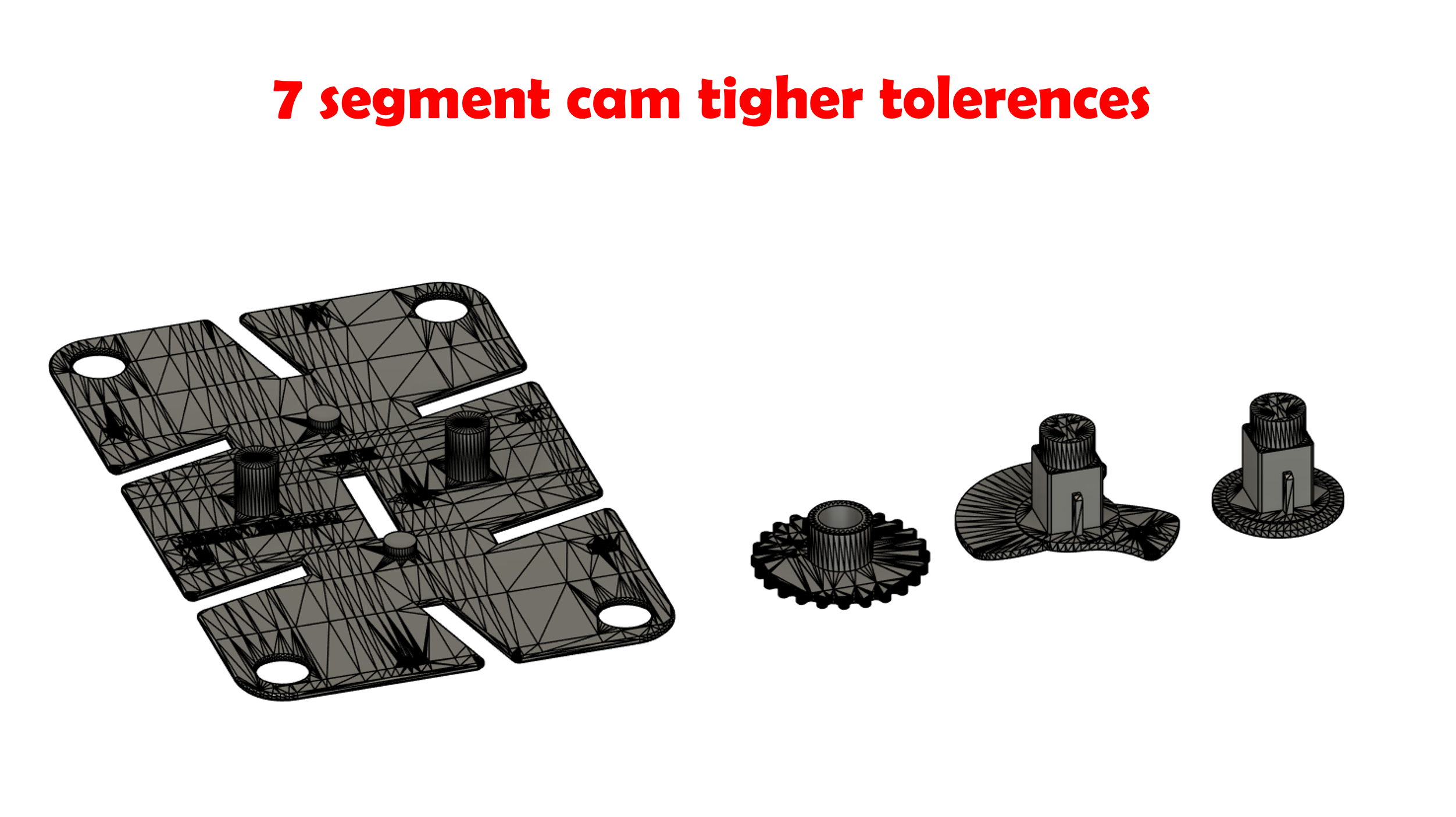
Mechanical 7 segment display with tighter CAM tolerences
by Bastien · via Printables
| Format | STL |
| Category | Art |
| License | CC BY-NC-SA |
| Uploaded | Jun 28, 2024 |
⬇ 37 downloads
❤ 3 likes
👁 424 views
Description
The original model was not tight enouth for me when using a precise printer. Made those changes: Made the SEG_PLATEpin for CAM 1mm taller. This make the cam jumping out of place les likely. Made the SYNC_GEAR hole smaller to have less play between the SYNC_GEAR and the SEG_PlATE. You can adjust it via the variable “syncGear_hole_thickness” in the fusion 360 model. Default diameter is at 8,1mm. Made the CAM_D1 and CAM_D2 hole smaller to have less play between the CAMs and the SEG_PlATE. You can adjust it via the variable “cam_hole_thickness” in the fusion 360 model. Default diameter is at 6mm. Made the CAM_D1 and CAM_D2 square bigger to have less play between the D cams and the A, B and C CAMs. You can adjust it via the variable “cam_square_thickness” in the fusion 360 model. Default diameter is at 0,15mm thicker than the original.
Originally published on Printables