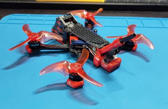
MetaFrame Pudge 2.5 (DJI O4 w Flywoo lensmod) mounts set and others
by AbaddoN__S · via Thingiverse
| Format | STL |
| Category | Mechanical |
| License | CC BY-NC-SA |
| Uploaded | Mar 22, 2026 |
⬇ 83 downloads
❤ 5 likes
👁 184 views
Description
A set of different mounts for a quadcopter based on the MetaFrame Pudge 2.5 + DJI O4 light air unit. The features: the FlyWoo lens-mod, JHEMCU JHE42B-S Finder buzzer and the BetaFPV F4 2-3S flight controller (with a tail). o4_flywoo_mount - mounts for installing an O4 light camera with a Flywoo lens mod. v1 - is the initial mount for standard assembly with screws (without screws it will also hold by the compression force) - the camera will "stick out" beyond the protective cheeks and rods. v2 - mount for installation without screws, the camera is "flush" with protective cheeks, nothing protrudes, the camera is completely recessed into the "body head". In this case, the back-top corner of the camera turns out to be too close to the upper plate of the frame - when the upper plate is "closed", the camera or cable can be damaged - therefore, I recommend sawing off parts of the plate that may damage the camera for easier installation - otherwise you will have to suffer... During assembly, I recommend gluing the pins into the side mounts or directly into the camera slots - they are not required, since when tightening the "cheeks" the camera will hold very tightly and securely without them, but with the pins it turns out to be installed in a guaranteed correct and permanent position (which, if desired, can be changed by modifying the model). unit_o4_shell_cover - protection of the DJI O4 unit so that protruding branches do not knock the smd components off the board and the camera cable\plug is not damaged. v1 - basic protection - a "visor" over the train and closed protruding parts of the unit. I did not make a completely solid coating so that ventilation and cooling were carried out normally. Protection of connectors from a set of plugs: https://www.thingiverse.com/thing:6909974 buzzer_back_pack - mount for the JHEMCU JHE42B-S Finder buzzer alarm system (which is why the development of this pack began). It is based on the assembly on the BetaFPV F4 2-3S 20A AIO FC V1 flight controller (powered by the "tail") - due to the "tail" of the FC, special assembly requirements arise. First, you need to remove the USB connector from the board, because it protrudes down too much and compact assembly will not work with it. After removing the connector, we solder thin wires and a jst-1.25 connector on the freed pins at the end (you can use another one, but I only have these now), after soldering we fix the wires on the board so as not to tear them off the tracks. The usb-jst connector is inserted into the side "pocket" of the buzzer - it is safe - well below the level of the blades (but you need to make sure that the wires do not stick out and are hidden inside the frame). The length of the antenna mount is made as long as possible and shifted sideways so as not to interfere with the installation of batteries (but the setpoint of the O4 unit can only be reached with a camera cable connector is facing forward, otherwise the antenna length will not be enough). v1 - the source mount for the boozer and antenna, nothing superfluous. v2 - mount for a buzzer, antenna, a 6.5x15mm capacitor, and an external USB connector on the JST-1.25. The capacitor is placed horizontally, since its length coincides with the height of the frame and no other option is possible. The capacitor is placed as high as possible, but nevertheless, during assembly, it will still interfere with the installation of the O4 unit - you need to assemble carefully and take your time. After assembly, the capacitor may rest against the silicone spacers, but the unit itself is 1-2 mm below it - everything is OK. v3 - mount for a booster, antenna, a 6.5x12mm capacitor, and an external USB connector on the JST-1.25. The capacitor is positioned vertically, at a minimum distance from the tips of the blades and the flight controller (there are no problems with installation and assembly). The order of assembly (it's not easy - everything is very tight): insert the XT30 connector into the hole between the antenna and the buzzer; insert the buzzer itself into the pocket; insert a connector with wires to connect the buzzer; install the standard O4 antenna; install the capacitor in the eyelets; insert the USB-jst connector into the "pocket"; install the flight controller with the assembled mount in the frame (the racks and screws on which the FC is mounted and the mount must already be screwed into the frame); install the O4 unit. Набор различных креплений для квадрокоптера на базе MetaFrame Pudge 2.5 + DJI O4 light air unit. Ключевые особенности - это линз-мод от FlyWoo, JHEMCU JHE42B-S Finder buzzer и полетник BetaFPV F4 2-3S (с хвостом). o4_flywoo_mount - крепления для установки камеры O4 light с линз-модом от Flywoo. v1 - исходный маунт для штатного крепления штатными винтами (без винтов также будет держаться от силы сжатия) - камера будет "выпирать" за пределы защитных щек и штанг. v2 - маунт для установки без винтов\саморезов, камера "заподлицо" защитных щек, ничего не выпирает, камера полностью утоплена в корпус. При таком варианте - задняя часть камеры получается слишком близко к верхней пластине рамы - при "закрытии" верхней пластины камеру или шлейф можно повредить - поэтому рекомендую отпилить части пластины, которые могут касаться камеры для более легкой установки - иначе придется помучаться... При сборке рекомендую вклеить штифты\пины в боковые крепления или непосредственно в пазы камеры - они не обязательны, поскольку при затягивании "щек" камера и без них будет очень плотно и надежно держаться, но со штифтами получается установка в гарантированно правильную и постоянную позицию (которую при желании можно изменить доработав модель). unit_o4_shell_cover - защита DJI O4 юнита, чтобы при крашах торчащие ветки не сбили smd компоненты с платы и не повредился шлейф камеры. v1 - базовая защита - "козырек" над шлейфом и закрытые выступающие части юнита. Полностью сплошное покрытие не стал делать, чтобы нормально осуществлялась вентиляция и охлаждение. Защита разъемов из набора заглушек: https://www.thingiverse.com/thing:6909974 buzzer_back_pack - кронштейн для аварийной пищалки JHEMCU JHE42B-S Finder buzzer (то, ради чего началась разработка этого пака). За основу взята сборка на полетном контроллере BetaFPV F4 2-3S 20A AIO FC V1 (с питанием на "хвосте") - из за "хвоста" ПК возникают особые требования к сборке. Во первых нужно снять usb разъем с платы, поскольку он слишком сильно выступает вниз и компактная сборка с ним не получится - после снятия разъема, запаиваем на освободившиеся пины - тонкие провода и разъем jst-1.25 на конце (можно другой, но у меня сейчас есть только такие), после пайки фиксируем провода на плате чтобы не оторвать их с дорожками. Разъем usb-jst вставляется в боковой "карман" бузера - он находится в безопасности - значительно ниже уровня лопастей (но нужно следить, чтобы провода от него не торчали и были спрятаны внутри рамы). Длина кронштейна антенны сделана максимально возможной и смещена вбок - чтобы не мешать установки батарей (но установка юнита O4 допустима только шлейфом вперед, иначе не хватит длины антенны). v1 - исходный маунт для бузера и антенны, ничего лишнего. v2 - маунт для бузера, антенны, конденсатора размером 6.5x15мм, и внешнего usb разъема на jst-1.25. Конденсатор размещается горизонтально, поскольку его длина совпадает с высотой рамы и другой вариант невозможен. Конденсатор размещен максимально высоко, но тем не менее при сборке он всеравно будет мешать установки O4 юнита - собирать нужно аккуратно и не торопиться. После сборки конденсатор может упираться в силиконовые проставки но сам юнит находится ниже него на 1-2 мм - всё ОК. v3 - маунт для бузера, антенны, конденсатора размером 6.5x12мм, и внешнего usb разъема на jst-1.25. Конденсатор располагается вертикально, на минимально удаленном расстоянии от кончиков лопастей и полетного контроллера (проблем с установкой и сборкой нет). Порядок сборки (это не просто - всё очень плотно и туго): провздеваем кабель с разъемом XT30 в проем между стойками, антенной и бузером; устанавливаем пищалку в карман; провздеваем кабель с разъемом пищалки тамже где и кабель питания; просовываем антенну O4 и вытягиваем её коннектор наружу; устанавливаем конденсатор в проушины; просовываем разъем usb-jst в "карман"; устанавливаем полетный контроллер с собранным кронштейном в раму (стойки и винты на которые надевается ПК и кронштейн должны быть уже вкручены в раму); устанавливаем юнит O4.
Originally published on Thingiverse