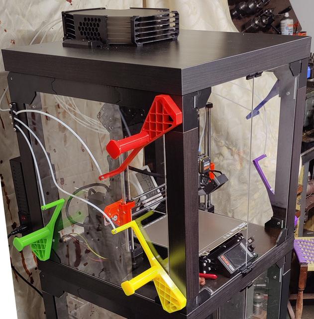
MMU3 compatible Ikea LACK v2 enclosure
by Matt · via Printables
| Format | STL |
| Category | Electronics |
| License | CC BY-NC-SA |
| Triangles | 4.1k |
| Uploaded | Jan 16, 2025 |
⬇ 31 downloads
❤ 11 likes
👁 698 views
Description
Please read before proceeding Please note this build uses parts remixed from two different sources that have two different licencing restrictions. Please check the additional parts listed at https://www.printables.com/model/1150836 to complete the set of parts used in this build, and ensure that if you are creating derivative works from any parts, that they respect the licencing restrictions from each original source as these two pages do. Introduction Before the official Prusa enclosures came out, there were instructions and files released to create an enclosure for the Prusa i3 MK3 with MMU2S system. Since then, the MMU2S has been replaced with the MMU3, and while the enclosure is still compatible with the newest i3 model MK4, the enclosure is incompatible with the MMU3 upgrade due to the change in alignment of the MMU's buffer inputs and outputs. This double-remix takes parts from the original v2 enclosure by Ondřej Stříteský https://www.printables.com/model/3673-prusa-enclosure-v2-mmu2s and the official Prusa enclosure MMU3 add-on https://www.printables.com/model/980267-mmu3-enclosure-addon and combines them to make the v2 enclosure MMU3 compatible. I've designed a few parts of my own to hold the buffer down to the lid without the use of magnets, and still allow the buffer to be removed for maintenance without damaging the enclosure lid by repeated unscrewing. Assembly instructions To start with, please ensure you are familiar with the Ikea LACK v2 enclosure assembly instructions here: https://blog.prusa3d.com/mmu2s-printer-enclosure_30215/ Basic assembly of the enclosure up to and including “Attaching the door panels” is the same, with two notable differences: Five of the corner pieces need to be replaced with the remixed versions in the “Remixed corners from Ikea LACK v2 enclosure” folder. These have additional holes in them that allow buffer spools to be mounted externally on the sides of the enclosure. Make sure you print them with supports in the necessary locations; you can confirm them with the v2 enclosure's .3mf files which have the support enforcers already in place. The lid part named “Prusa_MMU_enclosure_centering_part” will need to be repositioned slightly towards the back of the lid, so it doesn't interfere with the remixed corner piece. Everything after this point where the buffer and spools are attached are only relevant to the MMU2S, so can be ignored. Next, familiarise yourself with the layout of the MMU3-compatible Prusa enclosure as shown in the official Prusa assembly guide “Original Prusa Enclosure assembly (external display mounting)” at https://help.prusa3d.com/guide/6a-hinged-lid-with-mmu3_561868. You will need to print the official Prusa files for the enclosure buffer plate holder L and R, and enclosure buffer side L and R. These have holes for magnets, to reversibly attach the buffer to the Prusa enclosure's steel lid, but the Ikea LACK table isn't metal so leave those holes empty (they will be used later to secure the buffer to the lid physically). Also print 5x mmu_enclosure_spoolholder_R3_cap as these will be needed to complete the remixed spool holders in the next section. From the “Remixed spool and buffer management from Prusa enclosure” folder, you will need 5x spoolholder, 2x PTFE side holder, and 1x buffer mount. You will also need from the “New parts: Buffer retention clips” folder 2x bufferholder clip case and 1x each of bufferholder clip 1 and 2 (the clip case should be printed upside down, and will need support enforcers in the two large screw holes only). Additional to this, you will need to obtain some new PTFE tubing as the supplied MMU3 tubing from buffer to spools is too short to reach all the way round the side of any enclosure. You will need 5 lengths of 1.1m tubing, outer diameter 4mm and inner diameter hole 2.5mm, as per the official Prusa enclosure instructions. With reference to the photos in this build, align the buffer mount to the top of the lid, as far back as you can, and secure it in place at the rear of the lid using some small countersunk screws. This will avoid the central cavity that you have created on the inside of the lid for the MMU3's extruder Bowden tube. Modify the buffer as per the official Prusa enclosure instructions so it can lay flat on its side supported by the four new parts, and lay in place with the buffer wheel connector plate in the groove at the back of the lid's buffer mount. Prepare both bufferholder clip cases by screwing in an M3x10 screw fully into the “LOCK” hole. While this is in place, the clips are held in their fully extended position; to remove the buffer just undo the LOCK screw until the clips are free to be retracted, and the buffer will be removable. Make sure the clips are fully extended before inserting them into the holes either side of the buffer, or you'll have to unscrew the clip case from the lid entirely if you ever need to take the buffer out at a later date! Push the clip cases with attached clips into the holes on the sides of the buffer (one side has three slots, the other has four; each clip is designed to fit into one side). Fix the clip cases to the enclosure using the same pan head screws 5×20mm previously used in the v2 enclosure build. These screws should also avoid the central cavity, as the cavity is aligned closer to the front than the rear. With reference to the photos in this build and the official Prusa enclosure instructions, screw the PTFE side holders to the left and right rear enclosure side posts, near the top of the posts. Attach the 5x spoolholder caps to the 5x remixed spoolholders as shown in the official Prusa enclosure instructions, ensuring they are loose enough to spin freely. Then attach a spoolholder to each of the modified v2 enclosure corners using 2x M3x30 screws, aligning each holder so it points diagonally into the centre of the enclosure side panel. Thread the MMU3 PTFE tubes through the holes in the back panel and up to the buffer wheel outputs. Then take the 5x 1.1m PTFE tubes and connect from the buffer wheel inputs, through the side PTFE guides, and into one of the spoolholder caps (you may need to file each cap's hole slightly larger or splay it apart slightly with a slot screwdriver bit to push the tube through). Modifications complete, the enclosure is now ready to go!
Originally published on Printables