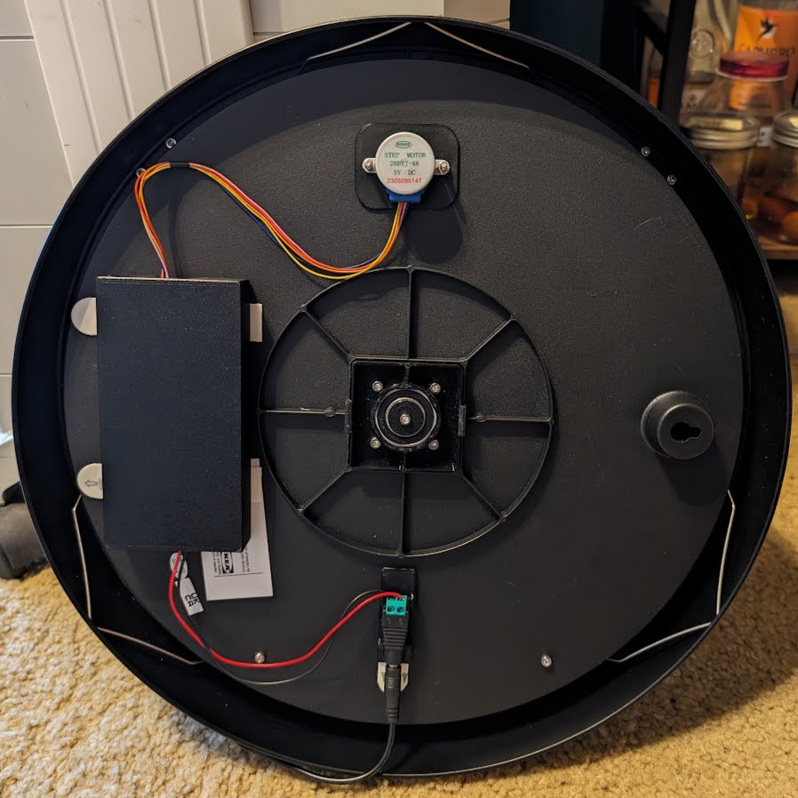
Mounting plate and enclosure for Wandering Hour Clock + Stepper Motor electronics
by IvyMike · via Printables
| Format | STL |
| Category | Art |
| License | CC BY-NC-SA |
| Triangles | 1.5k |
| Uploaded | Dec 20, 2023 |
⬇ 38 downloads
❤ 9 likes
👁 911 views
Description
This is a collection of 3d printed accessories for the "Improved Wandering Clock" with the "Wandering Hour Clock with Stepper Motor" and "Wandering Hour Clock w/Arduino + Wifi + Stepper Motor + Web Server" remixes. This collection includes: a mounting plate for the Arduino and Stepper motor driver an enclosure box for the electronics a mounting plate for a power connector an optional stiffener/mounting plate for the stepper motor These parts protect the electronics, make maintenance easier, and make the back of the clock look a lot tidier. Electronics mounting plate: For the mounting plate, I recommend these components: A 400 pin breadboard, 82x54x9mm. If you can find one thinner than 9mm, so much the better, but do not go any thicker. A ULN2003 5V Stepper Motor Driver Board. There are many variants of this component out there; see my photos to see the one you want. It measures approximately 31.5x35.5mm. Recommended: there are several different ESP32 boards you can use; I have "ESP-WROOM-32 module" which costs around $6 if you buy a pack of them. You can buy something else, just make sure it isn't too tall, and that it will fit on your breadboard. Four M3x4mm hex head screws. Longer screws will not fit. Electronics enclosure: The enclosure is designed to snap onto the mounting plate. It is sized to fit behind the clock. Unfortunately, clearance is VERY limited. This means you will NOT be able to use standard jumper wire to make connections, as they will stick out too far. I de-soldered the header pins from the ULN2003 and just soldered wires directly to the board. You can also try soldering directly to the pins. I do *not* recommend using wire wrap as the typical wire wrap wires are not rated to carry the current necessary to drive the stepper motor. Power connector mounting plate: The power connector mounting plate is designed for another generic but common DC Power Jack Plug. I bought this one: https://www.amazon.com/gp/product/B0BPGC5GTQ Other connectors might need changes to fit correctly. (Optional) Stepper motor mounting plate: The stepper motor mounting plate should not be necessary for most people, but is included just in case. Why would you want to use this part? It stiffens the back of the clock, and it makes sure the stepper motor holes are correctly aligned. I made a small error when drilling the holes for the stepper motor and had to enlarge one of the holes, which was a huge mess. The mounting plate attaches to the back of the clock to correct any such problems, and stiffen the back of the clock so everything aligns nicely. Note that this will cause the stepper motor shaft to effectively be shorter, and could cause problems attaching to the gear on the other side. I found that it was not a problem for me, but your mileage may vary. Bonus software: Bonus content: I also added new features to the clock firmware, allowing for fractional time zones, and enabling dynamic updating of time zone and DST status through the web interface. Until this has been tested by others and merged upstream, it should be considered beta software, but for the adventurous, you can get my version here on github . Thanks to: Ikea for creating the original Bondis clock clockspot ( @clockspot_44485 ) for creating the original Wandering Hour Clock model David Kingsman ( @DavidKingsman ) for creating the Improved Wandering Hour Clock model David Stern ( @DavidStern697247 ) for creating the Wandering Hour Clock with Stepper Motor remix and software Harshit Sanghvi ( @HarshitSanghv_582035 ) for creating the Wandering Hour Clock w/ Arduino + Wifi + Stepper Motor + Web Server remix and software Good luck and have fun making one of the most awesome clocks I've ever seen. If you build this, please post your make, I would love to see it!
Originally published on Printables