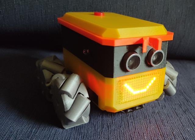
Otto Mecanum
by Alex Just Alex · via Printables
| Format | STL |
| Category | Other |
| License | CC BY-SA |
| Triangles | 20.2k |
| Uploaded | Jul 6, 2023 |
⬇ 254 downloads
❤ 50 likes
👁 2.5k views
Description
Otto Mecanum I wanted to build a 4wd Otto with mecanum wheels. I also wanted to try out the Pi Pico W, although it would be fairly simple to use other boards. The Pico W lends itself to control over WiFi so that’s the control route I decided upon, using RobRemo ( https://roboremo.app ) as my control app. I haven’t done much CircuitPython programming, so I also decided to code in CircuitPython. However while building I had stability problems with WiFi so I ported the code to MicroPython, with which I have no experience at all, but WiFi stability seems much better, Otto robots tend to be based around Arduino or esp8266 boards and the blockly programming environment. This design should be easy to adapt to suit an Arduino. There is also an implementation of blockly for the pi Pico https://rafaelaroca.wordpress.com/2021/03/03/block-based-programming-on-raspberry-pi-pico-with-bipes/ I used the waveshare pico servo driver board ( https://www.waveshare.com/pico-servo-driver.htm ) which measures 65 x 56 mm so there’s a fair amount of room for different board choices I took basic design inspiration from Otto Ninja I tried a few print in place mecanum wheels and these were the most successful: https://www.chiefdelphi.com/t/preassembled-3d-printed-2-mecanum-wheels/374184/96 . I modified them to mount with a servo horn. The support wedges can be cut off with snips or twisted off with pliers. I have designed an adaptor for pre-assembled mecanum wheels (from aliexpress) which do peform better than the print in place version. https://www.printables.com/model/519830-otto-mecanum-48mm-mecanum-wheel-servo-adaptor Printing: PLA 15% infil 0.2mm no supports You need to print 2 of each orientation of wheel. Bits & Bobs Raspberry Pi Pico W with header ( https://kitronik.co.uk/products/5345-raspberry-pi-pico-wh-wireless-with-header ), 4 continuous rotation MG90S servos an HC-SR04 ultrasonic sensor ( https://kitronik.co.uk/products/46130-ultrasonic-distance-sensor-hc-sr04-5v-version ), a kitronik line follower board ( https://kitronik.co.uk/products/5337-autonomous-robotics-platform-line-follower-board ) , a 16x8 LED matrix ( https://www.ottodiy.com/store/products/led-16x8-ultra-bright-matrix ) , this board is currently unavailable but I found the ‘OPEN-SMART 0.8" Inch 16x8 I2C LED Dot Matrix Display’ on aliexpress ( https://www.aliexpress.com/item/1005004399231415.html ) which works fine (note pin order is different) a couple of ir proximity sensors similar to these ( https://www.amazon.co.uk/Youmile-Infrared-Obstacle-Avoidance-Arduino/dp/B07PY3CVSV/ ) a generic buzzer ( https://kitronik.co.uk/products/3311-pcb-mount-buzzer-with-drive ) a push button switch. ( https://www.aliexpress.com/item/32822336474.html ) 2 x rechargeable 9v batteries ( https://www.amazon.co.uk/dp/B07NV4ZJ5Z ) 2 x battery connectors ( https://kitronik.co.uk/products/pp3-battery-clip-lead-heavy-duty ) A toggle switch ( https://www.aliexpress.com/item/1005003433590148.html ) Instructions for the build: 📷 Image redacted — claim this model to add your own media The base part has triangular supports in the holes for the servos, these can be removed by pushing outwards to break at the point and then inwards to snap off the triangle. 📷 Image redacted — claim this model to add your own media I didn’t design the break point terribly well so a little filing to clean up the edge may be required. Next position the servos and drop in the servo clamping piece. It’s a good idea to label the servo wires so you know which is which, then feed them up through the holes. 📷 Image redacted — claim this model to add your own media 📷 Image redacted — claim this model to add your own media 📷 Image redacted — claim this model to add your own media Connect wires to the toggle switch and fit this into the base, secure with a servo horn (trimmed short) 📷 Image redacted — claim this model to add your own media Now drop in the battery holder and secure this and the servo clamp with a couple of self-tapping screws passing through both. 📷 Image redacted — claim this model to add your own media Now put the led matrix in place and secure by screwing the retaining clip into the servo clamp with a small self tapping screw. 📷 Image redacted — claim this model to add your own media Thread the wires for the line follower sensor through from the bottom and clip the sensor into the mounting clip and attach the wires and then clip the mounting clip to the base. Now place the batteries and connect them up. (I have only ever used one battery). 📷 Image redacted — claim this model to add your own media Secure the PCB with 4 more self tapping screws. You can now connect the servos, buzzer, line follower and led matrix. (see wiring diagram in project photos) It's a good idea to connect the wires for the switch at this point also. 📷 Image redacted — claim this model to add your own media Mount the ultrasonic sensor and the ir proximity sensors into the mid section and attach their wires. Secure the ultrasonic sensor first Note I am powering the HC-SR04 with a 5v supply but the pico expects a 3.3v signal which is why I have a potential divider on the return (echo) signal. 📷 Image redacted — claim this model to add your own media I found it easiest to lift the clip that secures the ultrasonic sensor with a small screw driver. The ir proximity sensors are held with small self tapping screws. Connect these sensors to the board and clip the mid section to the base, feeding the switch wire to flop out the top and placing the buzzer wherever seems convenient. 📷 Image redacted — claim this model to add your own media Fit the switch to the top piece and hold in place with a servo horn, connect up the wires and clip it to the body. You can now clip on Otto's headband. (The ‘bow’ projects downwards). Screw servo horns to the wheels with self tapping screws and fit them to the servos. The two types are LR/RF for left front and right rear and RR/LF for right rear and left front. Micropython code and interface files for RoboRemo are to be found on github https://github.com/UEA-envsoft/Otto-Mecanum
Originally published on Printables