Powder Check Die
by SmallTarget · via Thingiverse
| Format | STL |
| Category | Tools |
| License | CC BY-NC-SA |
| Triangles | 1.0k |
| Uploaded | Mar 27, 2026 |
⬇ 16 downloads
❤ 1 likes
👁 65 views
Description
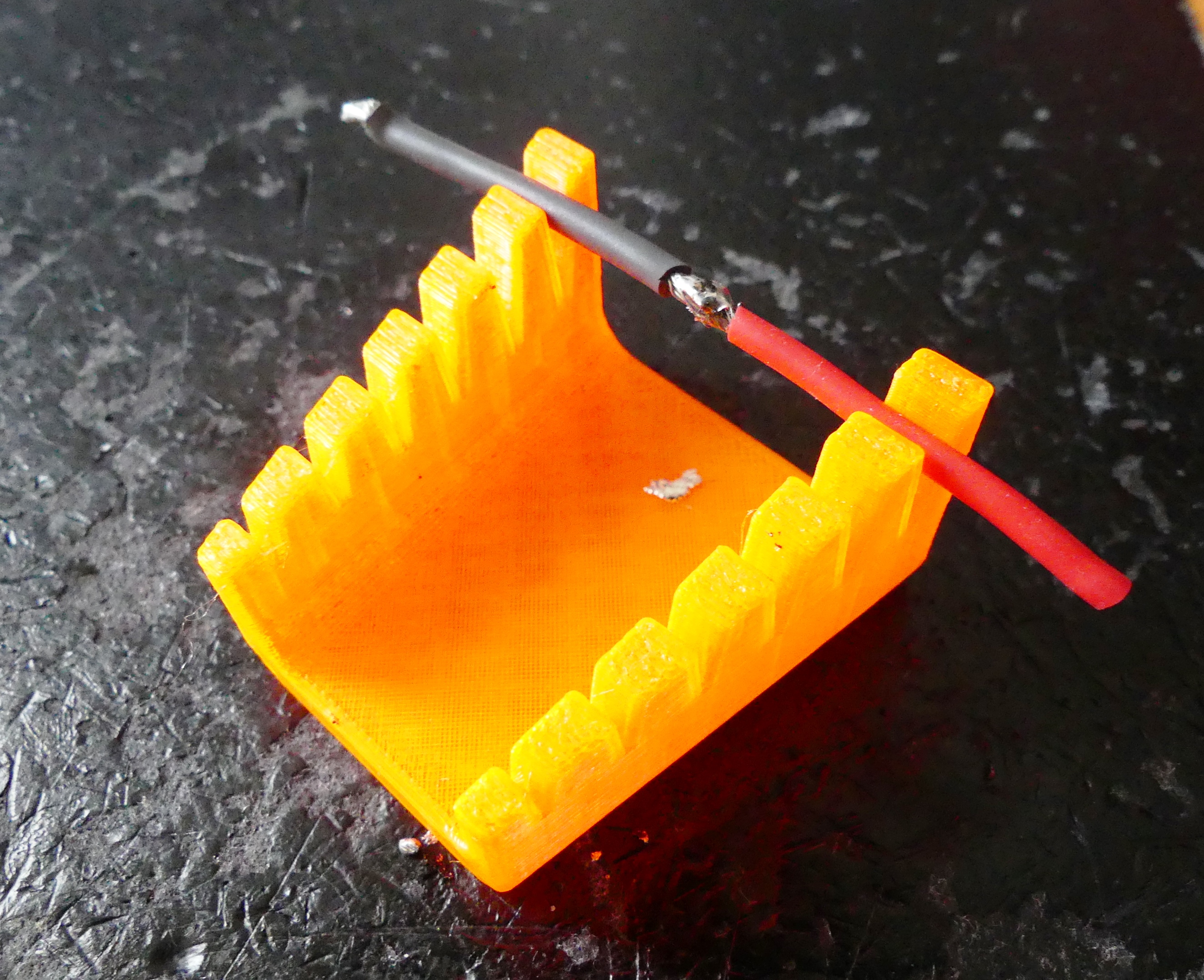
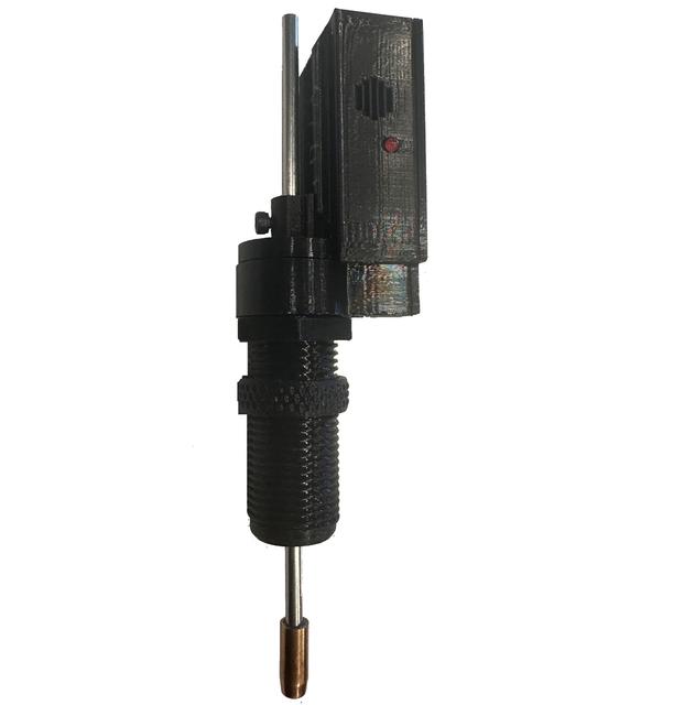
This is a powder check die that uses a battery, led and alarm with a reed magnet to sense the plunger atthe correct height. I wanted a powder check that beeps and lights a red LED when the powder in the case is outside of the settings. I bought 4 PCDs for my X-10 and none fit (it has very little room). So I designed and built this one with the electrical board as a "slip in" so you can wire outside the cover box and slip it in after you get your wires connected. If you want just one, probably just better to buy one, if you are like me and want one for each plate (preset to caliber then this will be very cost effective to build a number of them) This is a really fun project, and when it gets working it is very functional and fits about every press (including the FA X-10 which has almost zero room for a powder check) What you need: 1 x reed sensor (NC) 1 x Momentary switch 1 x 12V A23 Battery 1 x 12V red LED 1 x 12V Buzzer 1 x 4mm x 150 Steel rod 4 x 2mm x 8 screws 2 x 3mm x 6 screws A few inches of 22gauge solid core wire (or similar) The slip in board has “channels” on the back side to do your wiring (keeping the wires separated) Strip the wires and push through the holes in the "slip in board" and solder (or just assure they cram in the channel and touch, they do not move so I don't even solder them) For the rod, you want a 6.5 to 7mm tip as a wider area when pressing into the powder. You can cut a bullet and drill it out and hammer it in (I used a 6.5 Creedmoor) or you can buy a mix of brass rods and cut 14mm and drill/hammer it onto the rod. Magnetic Reed sensor (NC) $10 for 10 https://www.amazon.com/dp/B088CQL44X?ref_=ppx_hzsearch_conn_dt_b_fed_asin_title_1 Micro Limit Switch - $4 for 30 https://www.amazon.com/dp/B088W8WMTB?ref_=ppx_hzsearch_conn_dt_b_fed_asin_title_6 A23 Battery - $5 for 10 https://www.amazon.com/dp/B0D1CSS921?ref_=ppx_hzsearch_conn_dt_b_fed_asin_title_3&th=1 12V Buzzer - $8 for 15 https://www.amazon.com/dp/B07VX87W5Q?ref_=ppx_hzsearch_conn_dt_b_fed_asin_title_3 12V LED - $10 for 50 https://www.amazon.com/dp/B07Q17PVM4?ref_=ppx_hzsearch_conn_dt_b_fed_asin_title_4 Steel rod - $5 for 10 x 300mm that I cut in half for 20x https://www.amazon.com/dp/B0C5LV9QW9?ref_=ppx_hzsearch_conn_dt_b_fed_asin_title_4&th=1 Screws (lots) - https://www.amazon.com/dp/B0B6PVJTHY?ref_=ppx_hzsearch_conn_dt_b_fed_asin_title_18 Steps: 1: Cut the 4mm Steel rod in half and attack a 6.5mm to 7.3mm (brass) to one end 2: Wire the “slip in board) A: Strip and Pre-solder 2 solid core wires (one end) approx. 30mm and 16mm B: Set the reed switch in place and bend the reed switch wire to form a POS battery contact point C: Feed the other wire of the reed through the board and bend into the “Reed Channel (+)” C: Pre-Solder the common and “Closed” pins on the lever switch and screw in to board D: Feed 30mm wire through board at “Switch Channel In (-)” and bend around Neg battery post E: Feed 15mm wire through board at ‘Switch Channel Out (-)” and bend into channel slot F: Solder switch channel wires to lever switch so that it closes circuit when lever is pressed G: Strip and feed Pos and Neg wires for LED and Buzzer, feed though board and bend into channels 3: Slip the “Slip in board” into the “Electronic Box” and press the LED through the LED hole 4: Slide “Inner Sleeve” through the “Electronic Box” die hole and assure the trigger arm is below the switch lever 5: Slip the Die body over the “Inner Sleeve” and into the Box (tight fit) and slide the steel rod into place 6: Put battery into the box and assure when the “Inner Sleeve” is pressed upwards the alarms activate 7: Screw the retention screw into the “Setpoint Trigger” and slide over the Plunger Rod 8: Screw on the “Electronic Box” cover and start the box retention screw then screw into your press Adjusting / Setting the Powder Alarm 1: Place a case with the correct amount of powder into the press and lower the ram so the press is fully down 2: Screw the die into the selected die position just enough to trigger the alarm (then tighten the die nut) 3: Slide the “Setpoint Trigger” up or down the rod until the alarm stops 4: Tighten the “Setpoint Trigger” retention screw to hold the “Setpoint Trigger” in the correct position Unfortunate Legal Disclaimer: Reloading is dangerous and this tool is not a substitute for correct measurement and verification of proper safety and diligence in your process. Use at your own risk
Originally published on Thingiverse