Primary mirror cell for Hadley w/ slide-in hardware (M4 & #10 supported)
by JoshShabtaiCa · via Printables
| Format | STL |
| Category | Other |
| License | CC BY-NC-SA |
| Triangles | 8.9k |
| Uploaded | Dec 13, 2022 |
⬇ 122 downloads
❤ 14 likes
👁 1.2k views
Description
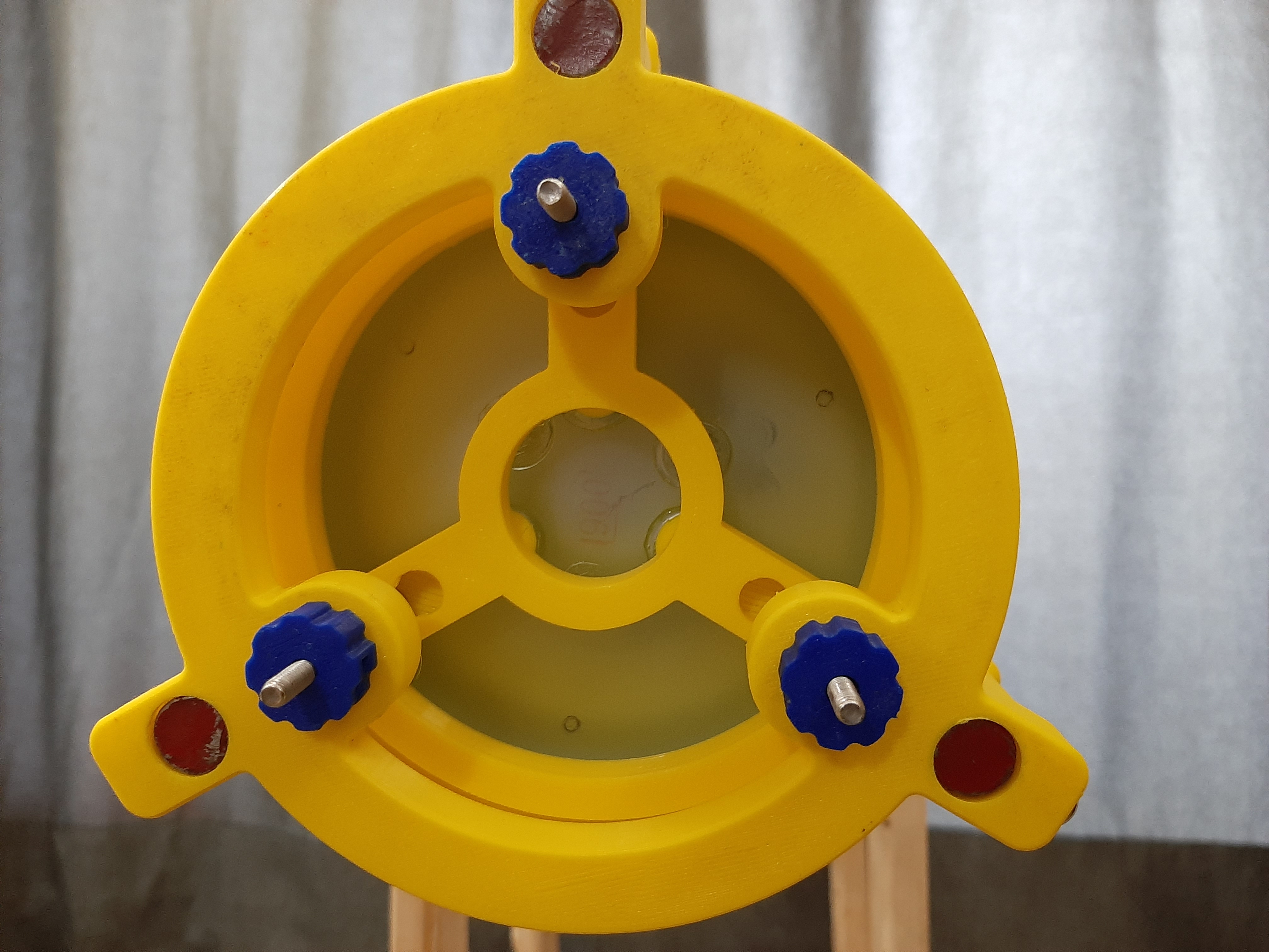
Print settings 0.6mm nozzle 0.32mm layer height 20% infill (but it probably doesn't matter too much) A test model is included so you can test that your hardware fits and that your printer settings are working, but this worked fine on my Ender 3. If you have any issues either leave a comment or message me and I'll try to help :) Background The original version of the primary mirror cell has the end of the screw poking out towards the mirror, with nothing to prevent you from pushing the mirror. In my case, I pushed the mirror right off (thankfully it didn't break!). I also didn't like the fact that you have to put the hardware in before gluing the mirror. I decided that a remix that has the screws “backwards” (with the head in the cell, and the end protruding out the back) would be better, and settled on this design that uses keyhole slots for the collimation screws. Hardware & assembly You can use either (be sure to download the right model for your hardware!): M4/#10 hex head bolts, or (this is untested, but should fit - please let me know if you try this so I can update this description) M4/#10 pan-head screws with a nut spun up to the top (this is what I did) Before assembly, make sure you have the following ready and in arms reach to minimize the amount of juggling you have to do: The LTA (not attached to the metal rods yet) The mirror cell 3 screws (either hex head or pan head with a nut, as described above) 3 knobs/wingnuts (I used [my M4 slotted knob](https://www.printables.com/model/270319-hadley-m4-knob-with-slot-for-nut). Be sure to have the nuts already installed if using this slotted model) 3 compression springs (I'm using bed springs since I have them handy from my 3d printer) Note 1 : If you've already glued the mirror, be extra careful not to touch the surface or let anything else touch it. Only handle it from the sides The reflective surface coating is quite fragile, and even wiping it with a soft cloth can be damaging. Note 2 : I recommend working over a soft surface (e.g. a bed, sofa, pillow) in case you drop your mirror. Hold the cell (from the sides!) upside down. Place a screw, head/nut down, in each of the three slots Place a spring on each screw Place the LTA over the mirror cell, lining up the screw. Most likely, the screws won't reach the holes before your fingers get in the way (unless you have really long screws). Once that happens, reach your other hand through the LTA to grab the cell by the inner ring. Once the screws are through the holes in the LTA, secure them with your knobs/wingnuts. You don't want things too tight, and you don't want to compress the springs all the way. You just want to compress the springs enough that they provide some resistance to keep things from spinning freely when you use/transport the scope. Other notes Bright yellow, like in my pictures, is a terrible choice to print optical components in, but it's what I have. As with the other telescope components, if you're not printing with a black filament (ideally matte), then you may want to paint it. In my experience though, as long as I'm not right next to a street lamp, it doesn't seem to have much impact for brighter objects like Saturn, Jupiter, and the moon.
AI Analysis: This is a mechanical part designed for use in a primary mirror cell system. It features a circular structure with three blue adjustment knobs and red indicator lights, allowing for precise alignment and adjustment of the mirror. The part is specifically engineered to support the M4 and #10 mounting hardware, making it essential for optical alignment in a telescope or similar astronomical instrument.
Originally published on Printables