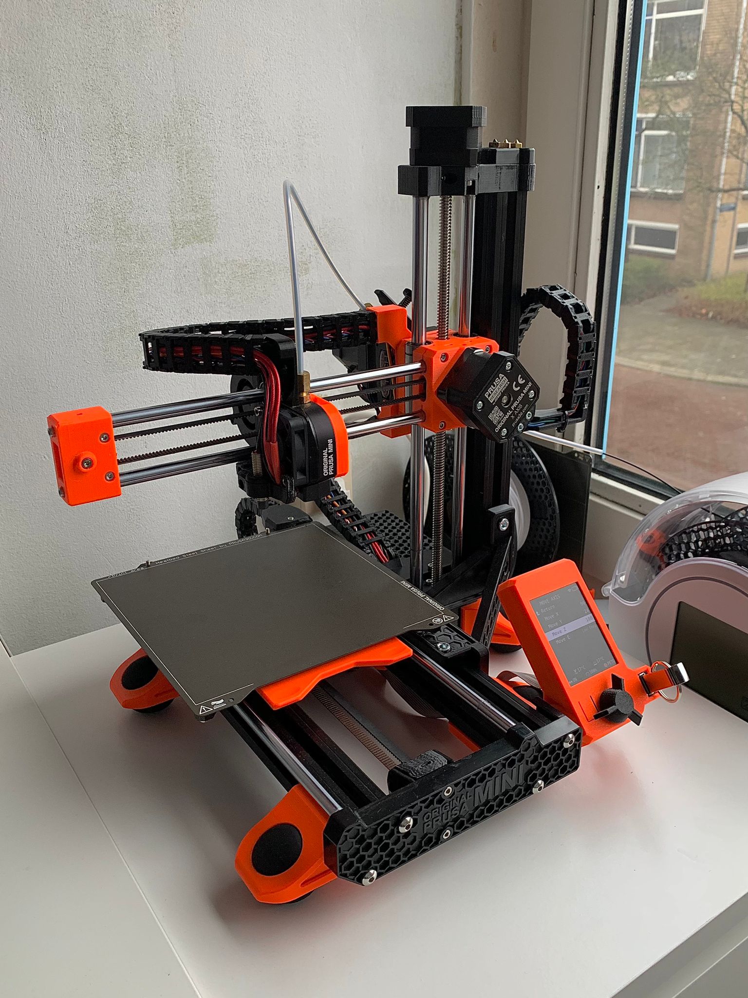
Prusa MINI/MINI+ Cable Chains and Mounts for all Axis
by Pandhabeer · via Printables
| Format | STL |
| Category | Art |
| License | CC BY-NC-SA |
| Triangles | 25.5k |
| Uploaded | Dec 21, 2023 |
⬇ 246 downloads
❤ 74 likes
👁 2.2k views
Description
A complete collection/model of Cable Chains and Mounts for all Prusa MINI/MINI+ Axis. I noticed that it was quite hard to find and install Cable Chains for all Axis of the Prusa MINI/MINI+, so here is my collection/model of mounts and cable chains including remixes and original parts for installing cables chains for all axis. All .STL files can be found in the file list, as well as some .SLDPRT (SolidWorks Part) files. Note: Some .SLDPRT might not be really pretty since SolidWorks doesn't really like meshes unfortunately… If you find my instructions/models/remixes/collection helpful please leave a like and make/rating :). Bill of materials: Print all the parts in the file list (The right quantities are mentioned in the title). 2x M3 nut 3x M3x10 bolt (In case you want to install the cable chains with a Bondtech Extruder:) 1x M3x45mm Bolt 1x M3x25mm Bolt (can be salvaged from original Prusa MINI/MINI+ Extruder). UPDATE (19/12/2023): I noticed that my MINI+ Z-carriage part warped a bit due to overtightening the M3x25mm Bolt. Be careful when installing :). I am currently testing an alternative bolt size for the M3x25mm Bolt. (In case you have installed the squash ball mod, no extra materials are needed and you can download the remixed squash ball foot in the file list or here . If you have not installed the squash ball mod the following parts are needed:) 6x Squash Balls (double yellow dot) 5x M6 x 12mm Bolts 5x M6 T-Nuts The files needed to install all Squash Ball Feet designed by @erickson85 can be found here . Note: it is not necessary to download and print the “Foot-eBox.stl” part since this part will be replaced by the remixed “Prusa MINI/MINI+ Squash Ball Foot with Cable Chain Connector for Y-Axis” part. Printing instructions: I would recommend printing all parts in PETG, 20% grid infill (just like the original Prusa parts). I think printing this mod in PLA is also possible, but some parts like the “1x X-Axis Heatbreak Mount” might deform due to the high temperature and need to be replaced eventually. These were my printing settings for installing these Cable Chains: Standard Prusaslicer PETG 0.2mm Quality print settings, infill 20% (Grid), no supports, 3 perimeters and printed with Prusament PETG. (Stock 0.4 Nozzle). Some parts needed support, in this case I used the organic tree support. Some extra printing instructions for the “1x Remix Cable Chain E-Box”: I sliced this model in PrusaSlicer, cut position: 5mm so I only needed support for the tiny bit of overhang (See last picture). I glued the parts together, but it als possible to print the part as one with support of course. Installation: UPDATE (21/12/2023): Forgot to mention that the linkage covers of the X-axis and Z-axis are a bit too big. You can bend those slightly (photo 10) for a more secure fit (be careful when doing this to not bend them too far). Unload any filament you have loaded (makes the install easier) Wait until the printend has cooled down in the meanwhile to the max Z-Height and at the end of the X-Axis (makes the install easier). Optional, but would recommend unplugging your MINI/MINI+ from the power supply. Remove all cable sleeves and zip ties from the printer and unscrew the top of the Electronics Box. (Optional) Remove the printhead PTFE Tube for easier acces to the extruder. Carefully unplug all the cables connected to the Buddy Board. X-Axis: Unscrew the Super Minda Probe, Heatbreak Fan and Cable guide carefully. Install the “1x X-Axis Heatbreak Mount” part with the same screws you just removed. Guid the cables through the Heatbreak Mount. Attach the printed Cable Chains and align and guide the cables through the Cable Chains. Note: make sure to take time to align the cables and leave a bit of slack in the cables (Otherwise closing the Cable Chain might not work). Use the “21x X-Axis Linkage Cover” parts to close the Cable Chain. XZ-Axis (With XZ-Axis I mean the cable coming from the X-Axis, photo 4): Place 2 M3 nuts in the “1x XZ-Axis Motor Mount Side P1” part and 1 M3 nut in the “1x T-nut” part. Use 2 M3x10 bolts to bolt the “1x XZ-Axis Cable Mount Cover” part to the “1x XZ-Axis Motor Mount Side P1” part. Bolt the “1x XZ-Axis Motor Mount Side P2” part to the “1x XZ-Axis Cable Mount Cover” part and slide the Cable Mount Cover over the X-Axis Motor (In my case this was a tight fit, perhaps scaling the part to 101% might solve this? The benefit of this tight fit is that no zip ties are required). Insert 1 M3 nut into the “1x XZ-Axis T-Nut” part and bolt the “1x XZ-Axis Z-mount” to the T- Attach the printed Cable Chains and align and guide the cables through the Cable Chains. Note: make sure to take time to align the cables and leave a bit of slack in the cables (Otherwise closing the Cable Chain might not work). Use the “15x XZ-Axis Linkage Cover” parts to close the cable chain. Note: the cable linkage covers seem a bit too big and bending the linkages slightly might help with the installation (See picture 10). Y-Axis: Unscrew the Y-Axis Heatbed Cable Connection and keep the screw of the Heatbed Connection. (Not completely sure if there was a zip tie, but in case of zip tie, cut the zip tie). Replace the original Y-Axis Heatbed Cable Connection with the “1x Heatbed Cable Connector” part, use the screw from step 1. In case of not using the Squash Ball Foot, install the “1x Cable Connector Frame (in case of not using squash ball foot)” part, otherwise install the “1x Remix Squash Ball Foot E-Box” part. Attach the printed Cable Chains and align and guide the cables through the Cable Chains. Note: make sure to take time to align the cables and leave a bit of slack in the cables (Otherwise closing the Cable Chain might not work). Use the “17x Y-Axis Linkage Cover” parts to close the cable chain. Guide the cables through the Electronics Box hole. (Picture 7). Extruder: Unscrew the original extruder. Install the “1x Remix Original Extruder” by dissasembling the original extruder, instructions can be found here . in case you have a Bondtech Extruder print the ”1x Bondtech P1” and “1x Bondtech Spacer P2” parts. Installation for the Bondtech Extruder Cable Chain Connection can be found here . Z-Axis: After unplugging all the cables from the buddy board, gently guide and align the cables through the Electronics Box Cover. Attach the printed Cable Chains to the Extruder Conection and align and guide the cables through the Cable Chains. Note: make sure to take time to align the cables and leave a bit of slack in the cables (Otherwise closing the Cable Chain might not work). Use the “23x Z-Axis Linkage Cover” parts to close the cable chain. Note: the cable linkage covers seem a bit too big and bending the linkages slightly might help with the installation (See picture 10). Gently push all cables in the Electronics Box and screw the “1x Remix Cable Chain E-Box” in place. Attach the cable chain to the Electronics Box. Congratulations on your “Prusa MINI/MINI+ Cable Chains and Mounts for all Axis” installation! If you find my instructions/models/remixes/collection helpful please leave a like and make/rating :).
Originally published on Printables