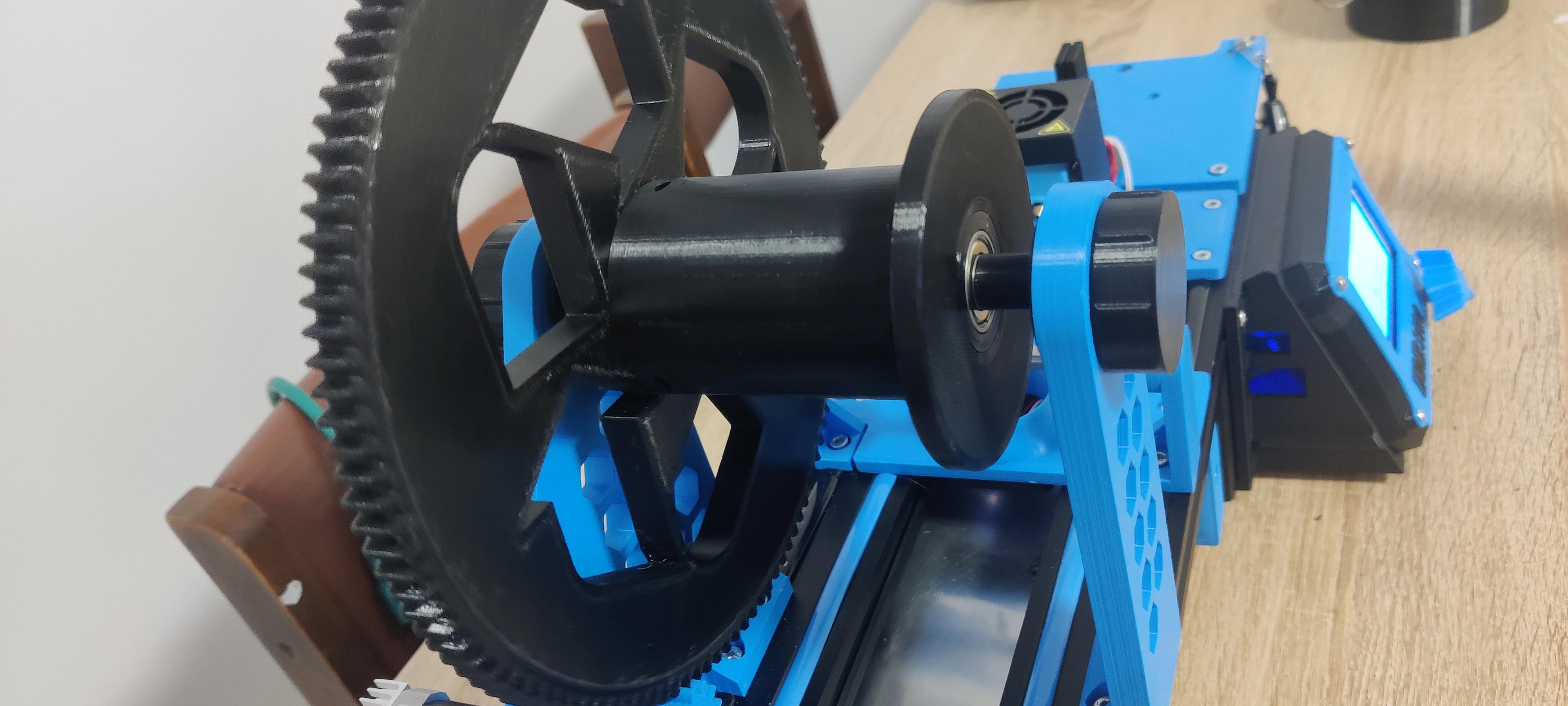
Recreator3D - bearing system on the spooler
by Bahoué · via Printables
| Format | STL |
| Category | Mechanical |
| License | CC BY-NC-SA |
| Triangles | 3.2k |
| Uploaded | Jan 23, 2023 |
⬇ 131 downloads
❤ 27 likes
👁 1.3k views
Description
ENGLISH: Setting up a bearing system on the large wheel : Materials required: 2x 608ZZ bearings 1x threaded rod 8mm diameter, 152mm long This system is added to the original system, avoids waste. 1. Print the bearing holder part in 2 copies. 2. Print the anti-tampering wedge 3. Print the threaded supports. The 2 are not identical, respect the direction. 4. The foot of axis opposite to the motor will be to turn over. It will be necessary to remove 0.6mm at the base because the holes of the 2 feet have a difference of this size. 5. Print the spacers, the 12mm one going on the motor side. Start by inserting the bearings in their supports (it should go in without forcing it). Then insert the brackets, one into the gear, the other into the opposite gear. The 2 are inserted on the outside. With the help of the threaded rod, insert the anti-locking wedge between the 2 bearing supports and screw them in. After having turned the foot opposite the motor 180°, insert the threaded supports by passing through the interior side, the holes being off-center be sure that the holes are the highest in the arm. You will see 2 lines on the part allowing to put well in the horizontal. The 2 threaded supports will need to be glued. Insert the threaded rod into the spacers and the wheel. Finish by tightening the threaded rod with a nut on each side (don't be too strong). Then use the printed plugs from the original bar to close the system. FRANCAIS: Mise en place d'un système de roulement sur la grande roue : Matériel requis : 2 roulements 608ZZ 1 tige filetée de diamètre 8mm, 152mm de long Ce système vient se greffer sur le système original, évite le gaspillage. 1. Imprimer la partie Support-roulement en 2 exemplaires. 2. Imprimer la cale anti-rapprochement 3. Imprimer les supports filetages. Les 2 ne sont pas identiques, respectez bien le sens. 4. Le pied d'axe opposé au moteur sera à retourner. Il faudra lui enlever 0.6mm a la base car les trous des 2 pieds ont une différence de cette taille. 5. Imprimer les entretoises. Commencez par insérer les roulements dans leurs supports (cela doit entrer sans trop forcer). Insérez ensuite les supports, l'un dans la roue crantée, l'autre dans la roue opposée. Les 2 s'insèrent du côté extérieurs. En vous aidant de la tige filetée, insérez la cale anti-rapprochement entre les 2supports roulements et vissez les tout. Apres avoir retourner a 180° le pied opposé au moteur, insérez les supports filetage en passant par le côté intérieur, les trous étant excentrés soyez sûr que les trous soient le plus haut dans le bras. Vous verrez 2 traits sur la pièce permettant de mettre bien à l'horizontale. Les 2 supports filetage nécessiterons d'être collés. Insérez la tige filetée dans les entretoises et la roue. Finissez en serrant la tige filetée avec un écrou de chaque côté (ne serez pas trop fort). Utilisez ensuite les bouchons imprimés de la barre d'origine pour fermer le système.
Originally published on Printables