(Un)original Prusa Heated Drybox
by Bram Elema · via Printables
| Format | STL |
| Category | Art |
| License | CC BY-NC-SA |
| Triangles | 4.2k |
| Uploaded | Aug 9, 2025 |
⬇ 1.6k downloads
❤ 811 likes
👁 23.1k views
Description
Disclaimer: This model has some flaws as described by the community, solutions to some of these flaws can be found under the remix tab. This can be quite a difficult project. Though it is possible to do without any prior knowledge, knowing what you are doing would definitely save you some headaches. Update July 18, 2024 Added a vertical display mount Update July 6, 2024 Relabelled the top Beam A1 & A2 to Beam A3 & A4 so it is easier to understand what parts to pick for your configuration. Functionally both parts are exactly the same. Added a troubleshooting section with a guide on how to identify the problem and a section where solutions to common errors will be placed Added a parts list with the parts of the (Un)original Prusa Drybox that have to be (re)used Update July 5, 2024 Slight revision of “Bracket X”, removed pinholes for the Arduino making it easier to align with the cutout for the USB-C port. Added “Bracket X_Long” which adds compatibility with the longer (37mm) MOSFETs provided by Blurolls. Update July 4, 2024 It turns out Blurolls is shipping two different versions of the mosfet, the electronics are the same however one is longer than the other and therefore doesn't fit in bracket X. The short version is 35mm long and does fit in the current model. The longer version is 37mm and a new model will be available asap, for now the remixed 3mf file by @MKEDan can be used Update July 3, 2024 Added schematics to the instructions for the electronics Will continue making the instructions more detailed Update June 18, 2024 Improved Beam A1 & A2 so the heat set inserts are easier to install. Update June 12, 2024 The electronic parts are now available through Blurolls ! About The (Un)original Prusa Heated Drybox is a heating add-on for the (Un)original Prusa Drybox. The heating add-on gives the extra functionality of drying wet filaments and even constantly heating to reduce the relative humidity. The add-on is available for both the CLASSIC and SLIM Edition of the drybox and is a good project for anyone who wants to learn how to solder and work with electronics. The heating system features a 200W PTC heating element in combination with two fans to blow hot air through the drybox. The heating system is located under the top panel of the drybox ensuring that the drybox still holds up to 6 spools with a diameter of 21 cm. Using the 2mm polycarbonate panels and with all 6 spools the heating system can reach temperatures of up to 45 degrees Celsius or 113 degrees Fahrenheit in 15 minutes making it perfect for drying multiple spools of PLA at the same time*. It can also reach temperatures of up to 65 degrees making it suitable for PETG**. * More specifications such as power consumption and heating graphs will be added in a user manual soon ** Keep in mind that it will take longer to heat with more spools Support If you like this or any of my other models consider buying me a coffee. https://www.buymeacoffee.com/bramelema If you donate over €5 as a thank you you will be added to a list of supporters below (write the name you want to see here in the comment box). Supporters #1 Mikko Laaksonen, #2 Vespercorp, #3 Anonymous, #4 Andrewlb.com, #5 Peter from Blurolls, #6 Walter Bracke, #7 Alex Krasno, #8 Sarah, #9 Greg & Maud, #10 Arcaik, #11 Joost, #12 Psych0h3ad, #13 T. J. Domsalla, #14 Photastro, #15 Anonymous, #16 Ment57, #17 Jim Callahan, #19 Werner, #20 Svaar Caldersson, #21 Bronco7794, #22 CowboyWillT, #23 Filip, #24 Kukulin, #25 mdandersen, #26 Anonymous, #27 Dennis, #28 JT, #29 Thomas Trueten, #30 Kilsgaard Special thanks to #18 WBSP Thank you everyone for your support! Buy the electronics The parts for this project are available through Blurolls and can be bought here: Blurolls or Aliexpress (electronic parts and screws, optional PSU) Note: I receive a small portion of each sale which helps me develop future projects like this one Gallery 📷 Image redacted — claim this model to add your own media 📷 Image redacted — claim this model to add your own media 📷 Image redacted — claim this model to add your own media Print settings I recommend printing with 3 walls and 25% infill. The parts are designed to be printed with a 0.2mm layer height. The parts have already been placed in their optimal orientation. Most parts have to be printed with some supports however they are designed to be printed with little and easy-to-remove supports. Bill of Materials The BoM is the same for both editions of the drybox. A kit with the Electronic parts and Screws will be available through Blurolls soon Filament If you already have a drybox and need to print the replacement parts, the printable parts add up to around 550 grams of filament when using 3 walls and 25% infill. When printing a new drybox around 325 grams of filament is used on top of the filament for the drybox itself. Since the drybox is being exposed to heat using PETG, ABS, or ASA is required for both the drybox and the heating addon. Due to the heater being mounted to “Bracket Y” it is highly recommended to print this part in ABS or ASA. Electronic parts Part: Amount: Picture: 24V 200W PTC Heater1 📷 Image redacted — claim this model to add your own media 24V 350W PSU1 📷 Image redacted — claim this model to add your own media 0.96 Inch OLED screen 1 📷 Image redacted — claim this model to add your own media 6*6*5mm Tactile Pushbutton3 📷 Image redacted — claim this model to add your own media Arduino Nano V3.0 (clone) USB Type C1 📷 Image redacted — claim this model to add your own media 5-36V 15A Mosfet1 📷 Image redacted — claim this model to add your own media LM2596 Buck Converter1 📷 Image redacted — claim this model to add your own media DHT20 Temperature Sensor1 📷 Image redacted — claim this model to add your own media 24V 4010 Fan2 📷 Image redacted — claim this model to add your own media 16 AWG / 1.3mm2 Copper wire 2.5 Meter C14 Chassis Connector1 📷 Image redacted — claim this model to add your own media C13 Power Cable, 2 Meter (plug type depends on your country) 1 📷 Image redacted — claim this model to add your own media Screws On top of the screws in your drybox 10 M3*8 screws are needed, 19 M3*12 screws, and 2 M4*6 screws. There are also 35 M3 heat-set inserts needed, For the threaded inserts I accounted for the ones from Ruthex, they require a hole with a diameter of 4mm and a depth of 5.7mm but other brands would also work. Tools Volt meter (multimeter) (you shortly need this to calibrate the buck converter) Soldering iron H2.5 & H3.0 hex keys Wire cutters Wire strippers (a scissor, knife, or wire cutters can also be used for this but be careful) Hot glue gun Consumables Soldering tin Some wires (optional) Female-female jumper wires instead of some of the regular wires Printed parts Name: Amount: Notes: Beam A3_Heater1 This is a replacement for the top “Beam A3” in your existing drybox. If you are printing a new drybox, print this one instead of the regular one. Beam A4_Heater1 This is a replacement for the top “Beam A4” in your existing drybox. If you are printing a new drybox, print this one instead of the regular one. Beam G1_(SLIM)/ (CLASSIC)_Heater1 Choose “_SLIM” when using the SLIM Edition of the drybox use “_CLASSIC” for the CLASSIC Edition This is a replacement for “Beam G1_(Humidity)” in your existing drybox. If you are printing a new drybox, print this one instead of the regular one. Beam G2_(SLIM)/ (CLASSIC)_Heater1 Choose “_SLIM” when using the SLIM Edition of the drybox use “_CLASSIC” for the CLASSIC Edition This is a replacement for “Beam G2_(Humidity)” in your existing drybox. If you are printing a new drybox, print this one instead of the regular one. Bracket X_(Long)1If your MOSFET is 35mm long, choose for “Bracket X”. If your MOSFET is 37mm long, choose for “Bracket X_Long”Bracket Y1 This remix has improved mounting for the heating elementBracket Z1 Display 1_(Vertical)*1Use “_Vertical” for a vertical displayDisplay 2_(Vertical)*1Use “_Vertical” for a vertical displayPSU_Mount1 PSU_Cover_(Switch)1“_Switch” can be used with a ~13*19 mm power switchChannel_Short1 Channel_Cover_Short1 Channel_Long1 Channel_Cover_Long1 Channel_Cover_Corner1 Channel_Cover_End1 * When using a vertical display I highly recommend checking out this improved model by @WBSP! (Un)original prusa drybox: If you are printing a new drybox you don't have to print all of the parts for the frame, the parts you do need to print are listed below (for the most part the same for the SLIM and CLASSIC Edition). These parts can be found here . Name: Amount: Notes: Beam A1_(Throughput) /(PC4-M10)1“_Throughput” adds holes in the bottom back to put a PTFE tube through. “_PC4-M10” replaces the optional throughput holes with PC4-M10 fittings.Beam A2_(Throughput) /(PC4-M10)1“_Throughput” adds holes in the bottom back to put a PTFE tube through. “_PC4-M10” replaces the optional throughput holes with PC4-M10 fittings.Beam B2 Beam C1_(RB)(20mm)1“_20mm” is made for using 20mm diameter rods instead of the regular 18mm ones. “RB” makes the drybox compatible with this raised RepBox 2.5 mount.Beam C2_(RB)(20mm)1“_20mm” is made for using 20mm diameter rods instead of the regular 18mm ones. “RB” makes the drybox compatible with this raised RepBox 2.5 mount.Beam D2 Beam E11 Beam E21 Beam F1_(Standalone)1“_Standalone” adds the standalone featureBeam F2_(Standalone)1“_Standalone” adds the standalone featureCorner A4 Corner B11 Corner B21 Corner C11 Corner C21 Assembly The installation process is the same for both versions. The instructions below show images from the CLASSIC Edition but the parts from the SLIM Edition are labeled the same. 1) Disassembling the old drybox If you are building a new drybox you can skip to the second part of the assembly The first step in preparing the drybox is to remove all filament spools, desiccant boxes, PTFE tubes, the two rods, and anything else that isn't screwed in. Once the drybox is stripped remove the door by unscrewing the hinges and the “Hinge_connect” pieces that connect it to beams G1& G2. Then remove the top, back, and side panels. The bottom panel doesn't have to be removed. Unscrew the top screw on all of the vertical beams (beams B and E). Once this is done the top part of the frame should come off. The bottom part of the drybox and the panels can be set aside as we will work with the top frame first. Finally, remove Beam G1 & G2 and Beam A1 & A2 from the top frame and remove all the nuts. Since we will be replacing these beams they can be discarded or kept as spare parts. 📷 Image redacted — claim this model to add your own media The bottom of the frame and the remainder of the top frame should look similar to these images. 📷 Image redacted — claim this model to add your own media 2) Heat-set inserts Insert the threaded inserts in the correct places using a soldering iron. 📷 Image redacted — claim this model to add your own media Install a total of 5 heat-set inserts in the following way in beams A3 & A4 Note that two have to be put in at an angle. Although it may look difficult it is not, just put the heat set insert on the soldering iron first and then push it in. 📷 Image redacted — claim this model to add your own media Install the heat-set inserts in the following way in beams G1 & G2 📷 Image redacted — claim this model to add your own media Install the heat-set inserts in the following way in Bracket X Install 14 heat-set inserts in the following way in Bracket Y 📷 Image redacted — claim this model to add your own media 📷 Image redacted — claim this model to add your own media 📷 Image redacted — claim this model to add your own media Install the two heat-set inserts in the following way in Bracket Z (in the two protruding cylinders) 📷 Image redacted — claim this model to add your own media The heat-set inserts for the PSU mounting parts and screen can be installed like this 📷 Image redacted — claim this model to add your own media 📷 Image redacted — claim this model to add your own media 3) Electronics During this part of the assembly, you are going to do most of the soldering and work with the voltmeter. If you are not sure how to solder you can watch this video, soldering can be quite tricky at first but you get used to it pretty quickly. If you are new to using a voltmeter this video explains quite well how to use one. In the image below a schematic of the electronic circuit can be seen. Some parts may look a bit different in the schematic but the pins are labelled in the same way. In the steps below there is both a visual and textual explanation of the assembly. 📷 Image redacted — claim this model to add your own media 📷 Image redacted — claim this model to add your own media 📷 Image redacted — claim this model to add your own media 📷 Image redacted — claim this model to add your own media 📷 Image redacted — claim this model to add your own media 📷 Image redacted — claim this model to add your own media 📷 Image redacted — claim this model to add your own media The first step is to solder the pins to the Arduino Nano, here only the two long strips have to be soldered to the Arduino with the long side of the pins on the side with the USB C port. 📷 Image redacted — claim this model to add your own media Once those have been soldered the screen and the three buttons can be placed in the “Screen 1&2” as shown in the image and then sandwiched between them. Solder wires to the buttons as shown in the schematic and images. The loose ends should be about 8 centimetres. Also, connect four wires of the same length to the pins of the screen. Screw the fans and PTC Heater in bracket Y using 8 M3*16 screws for the fans and 4 M3*12 screws for the PTC element. The wires for the fan can be guided through the hole in the printed part Note: make sure the wires from the PTC element are on the side with a hole for them (as seen in the image). Note: for the fans make sure the air is blowing towards the printed part, so the sticker has to be on the inside. Screw the 16 AWG wire into the input side of the MOSFET, the MOSFET has to be oriented upside down. Solder 2 wires to the positive and negative input of the BUCK Converter, these wires have to be around 4/5 centimetres long. The other ends can be screwed into the input terminals of the MOSFET where we just screwed in the 16 AWG wire. Make sure that the positive input of the BUCK Converter is connected to the positive input of the MOSFET, the same goes for the negative input. Once this is connected it is time to use the Volt meter. Connect the probes of the Volt meter to the output of the BUCK Converter, then connect the long wires that are connected to the MOSFET and BUCK Converter to the power supply and connect the power supply to the C13 chassis connector. Before connecting the power cable and plugging it in an outlet make sure your power supply is set to the right input voltage for your country, if that is correct it can be plugged in and you can start rotating the screw on the buck converter until the output voltage reaches 5 Volts. Warning! When the circuit is plugged in high voltages and currents can be on the exposed wires so do NOT touch those, if you think anything is wrong immediately unplug the power cable. With the BUCK Converter correctly set up, the voltage meter can be put aside and all cables disconnected from the power supply 📷 Image redacted — claim this model to add your own media After that, connect the positive and negative output pins of the BUCK Converter to the Vin and GND pins of the Arduino as shown in the schematic on the left Connect the GND of the MOSFET to the GND pin on the Arduino and Connect the signal (TRIG/PWM) to Pin D10 Connect the GND of the buttons (the 3 connected wires) to the GND on the Arduino and Connect the other cables to pins D6, D7, and D8 on the Arduino, D6 being the cable closest to the Arduino. Connect the GND and Vin pins of the screen to the GND and 5V pins of the Arduino. The SDA pin can be connected to pin A4 and SCL to pin A5. 📷 Image redacted — claim this model to add your own media 📷 Image redacted — claim this model to add your own media Solder 4 cables with a length of 10 cm to the pins of the temperature sensor. After that insert the temperature sensor in Bracket Z as shown in the image to the left, and make sure that the holes are pointed upwards. Connect The pins in the same way as the pins from the screen, it is okay to solder multiple cables to one pin on the Arduino. Looking from the front (side with the holes) with the pins on the bottom, the pinout of the temperature sensor is as follows: VDD → 5V SDA → A4 GND → GND SCL → A5 📷 Image redacted — claim this model to add your own media Cut the PTC and fan wires to size and screw them into the positive and negative output terminals of the MOSFET, for the fans, the red cable needs to be connected to the positive line and black to the negative one, for the PTC it does not matter. With the wiring being done connect Bracket X and Y using 2 M3*8 screws, Bracket Z can also be attached using 4 M3*8 screws. 📷 Image redacted — claim this model to add your own media 4) Assembling the top frame With most of the electronics being installed the top frame can be re-assembled using M3*8 screws. Once this is done the top panel can be screwed back in place using the M3*8 screws and nuts. Note: when installing Beam A2 make sure that the two wires that lead to the power supply go through the hole. 📷 Image redacted — claim this model to add your own media 5) Connecting the frame Connect the top frame to the bottom part we had before using 4 M3*8 screws. With the frame being complete the remaining panels can be installed using M3*8 screws and nuts, when installing the back panel don't install the 5 screws on the left half of the panel (when looking from the back), we will be installing the power supply here during the next steps. 6) Mounting the PSU & finish connecting the electronics 📷 Image redacted — claim this model to add your own media Install the PSU mount in the bottom left using 2 M3*12 screws and install the cable guides using 3 M3*12 Install the power supply in the PSU mount using 2 M4*6 screws The cables can then be guided through the guides which can then be closed using the lids Note: it can be easier to guide the cables if you bend them using some pliers Install the C13 connector using 2 M3*8 screws Connect the cables from the drybox to the V+ and V- terminals of the PSU, using a short piece of wire also connect the C13 connector to the L and N terminals of the PSU. Finally, close the PSU mount using 2 M3*8 screws Congratulations!! That is it for the hardware now we will move on to uploading the code to the Arduino 7) Programming First, connect the Arduino Nano to your computer using a USB type C cable, the USB-C port of the Arduino is located on the right side of the controller hub (Bracket X). For this step, the drybox doesn't have to be plugged in yet. Open the provided code in Arduino IDE In Arduino IDE choose the Arduino Nano as the output board and make sure the right com port is selected, IDE should automatically select the right one. Install correct libraries Select whether you want the temperature to be in Celcius or Fahrenheit. By default Celcius is selected, to use Fahrenheit remove the “//” in front of line 18. Upload the code to the Arduino, If everything is correct the screen should light up. If everything works unplug the USB cable and plug the C14 cable into the drybox and then into an outlet. The screen should turn on again and based on the target temperature the heating element should turn on. Done! Troubleshooting Still not working? No worries, in this section you will find common problems and instructions on how to locate the problem. Common problems 1) The code doesn't load to the Arduino Often this happens because the Arduino has to be set to “old bootloader” Open Arduino IDE and plug in your Arduino Nano Make sure the board is selected as Arduino Nano 📷 Image redacted — claim this model to add your own media Then go to Tools → Processor → ATmega328 (Old Bootloader) 📷 Image redacted — claim this model to add your own media Try uploading the code to the Arduino The issue should be solved now, if the issue does persist please leave a comment and I or others will help you. Locating the problem using test code In the file section, there is a folder with troubleshooting code to test the individual electronics. Unplug the PSU from the outlet and connect the Arduino to your PC. Check whether a light turns on on the Arduino If a light turns on Upload the first code “Screen_Testing” to the Arduino, if the screen works as intended the (Un)original Prusa Drybox logo should be visible. Upload the code “Buttons_Testing” to the Arduino and open the Serial Monitor in Arduino IDE and make sure the baud rate is set to 115200 (The Serial Monitor can be found in the top right of your screen). First of all, you should see a message “Button Testing”, after that start pressing the buttons and the Serial monitor will send a message about which button is pressed. If all three of the button give the correct output move on to the next step. Upload the code “TempSensor_Testing”. With the Serial Monitor open it should display the current temperature and humidity. Upload the code “Heater_Testing”. Unplug the Arduino from your PC and plug the PSU into an outlet. First of all, check if a light turns on on the Arduino, check if the light turns on on the MOSFET, check if both fans are spinning, and finally, check whether the PTC element is heating, do this by holding your hand close to it but DO NOT touch the element itself. Now you have most likely found your error, first of all, it is always good to check if the wiring to that component is good. If everything seems okay but it still doesn't work please leave a comment with pictures and the problem you identified. I and others will be more than happy to help you.
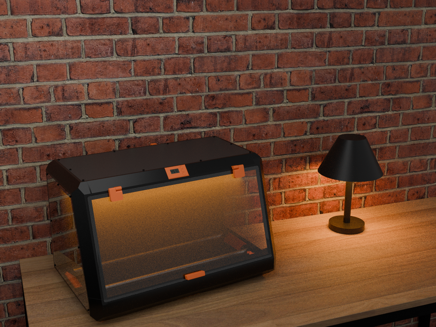
AI Analysis: This is a mechanical part designed for storing and heating filament for . It features a transparent front panel and a black exterior with orange accents, providing a secure enclosure for the filament spool. The unit includes a heater element to maintain optimal temperature for , making it a functional storage and heating solution for filament.
Originally published on Printables